iCE40 FPGA iCE aStick with IceStorm Tutorial

Lattice iCE40 FPGA IceStorm Tutorial

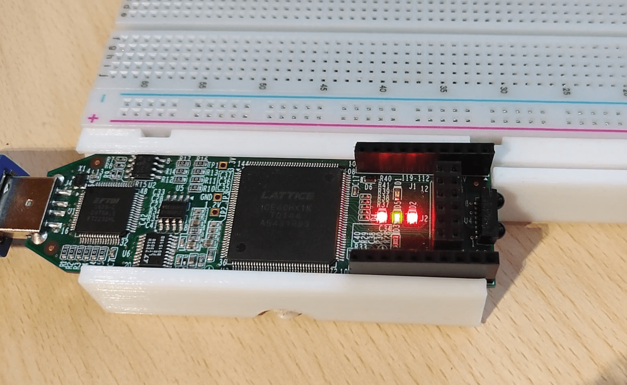
This tutorial will cover the hardware and software setup for the icestick development board that uses an iCE40 FPGA. The IceStorm open source toolchain will be used for programming the board instead of the vendor tools. For the demonstration, we’ll make a simple binary counter that will display its value with the onboard LEDs. The logic design will be defined/coded with Verilog.

Raspberry Pi Microscope

DIY Raspberry Pi Microscope

In this post, I’ll show you a Raspberry Pi microscope I made for soldering and inspecting PCBs. The great thing about it is that it has a long working distance. This enables the microscope to be mounted on the shelf above my workbench so it doesn’t get in the way. An additional benefit is that the image doesn’t shake if you bump the table when working.

Attiny 85 Digispark Board

In this post, I’ll show you how to use and program the Attiny 85 Digispark board with the Arduino IDE. I’ll demonstrate how to add the board to the Arduino IDE and how to install the drivers. Finally, we’ll make an example sketch that simply blinks an LED.

DIY Arduino SD Card Reader

Arduino SD Card Reader

In this post, we’ll see how to make an SD card reader shield for the Arduino. It’s pretty simple as it’s just a matter of connecting the proper Arduino pins to the correct pads on the SD card adapter. Additionally, resistors need to be added for certain pins. These will form voltage dividers that will drop down the signal voltage for the SD card from 5V to around 3.3V.

DIY SMD Vacuum Pickup Tool 2

DIY SMD Vacuum Pickup Tool

In this post, I’ll show my DIY SMD vacuum pickup tool. I bought this vacuum pump SMD pickup but it had no way to be turned on/off. There is only a hole on the vacuum “pen” that you can cover with your finger to make or release the vacuum. I decided I would mod it and make it operable with a footswitch. When pressed the vacuum pump is turned on and when you let go the vacuum pump is turned off while the valve is opened at the same time to release the vacuum and instantly drop the SMD part from the nozzle.

diy solder paste dispenser

DIY Solder Paste Dispenser

In this post, I’ll show my DIY solder paste dispenser. It’s powered by a 12V adapter and can be operated by a footswitch(connected via banana connectors). It uses a small membrane air pump/compressor to dispense the solder paste/flux. Additionally, there is a solenoid air valve connected to the airline so the pressure can be released after you let go of the footswitch which prevents the solder paste or flux from oozing out. The pump and valve timing is controlled through a relay module by an attiny45 microcontroller.

ALU the A and B Registers

8-Bit Computer ALU And The Flags Register

In this post, I will talk about the ALU and the flags register of my 8-bit computer. The arithmetical logical unit(ALU) is where all the computation happens in a computer. The ALU of this computer is very simple and only has the option to add or subtract numbers. So something like multiplication would have to be implemented in software.  The flags register stores the Carry(a carry occurs) and Is Zero(the result is a zero) flags that it receieves from the ALU. 

button debounce module

8-Bit Computer Button Debouncing

In this post, we’ll take a look at the button debounce module of my 8-bit computer. Ben used a 555 timer in his clock module to make a delay to debounce the button. I took a different approach. I took the 50 MHz input from the crystal oscillator and lowered the frequency by using another clock module. This way I have another slower clock signal independent from the main clock. This slow frequency is then fed into the debounce modules.

clock module

8-Bit Computer Clock Module

In this post, we’ll take a look at the clock module of my 8-bit computer. Ben used a 555 timer in his clock module to generate the clock signal for his breadboard computer. The approach I took is a bit different. The DE0 Nano FPGA development board has an onboard 50 MHz crystal oscillator connected to one of the pins of the FPGA. This is where we can get our clock signal from. The problem is that the frequency is way too high for the computer and needs to be lowered. This can be accomplished by dividing the frequency using a frequency divider(which is esentially just a ripple-carry counter) or by using a PLL(phase locked loop).

Advertisment ad adsense adlogger