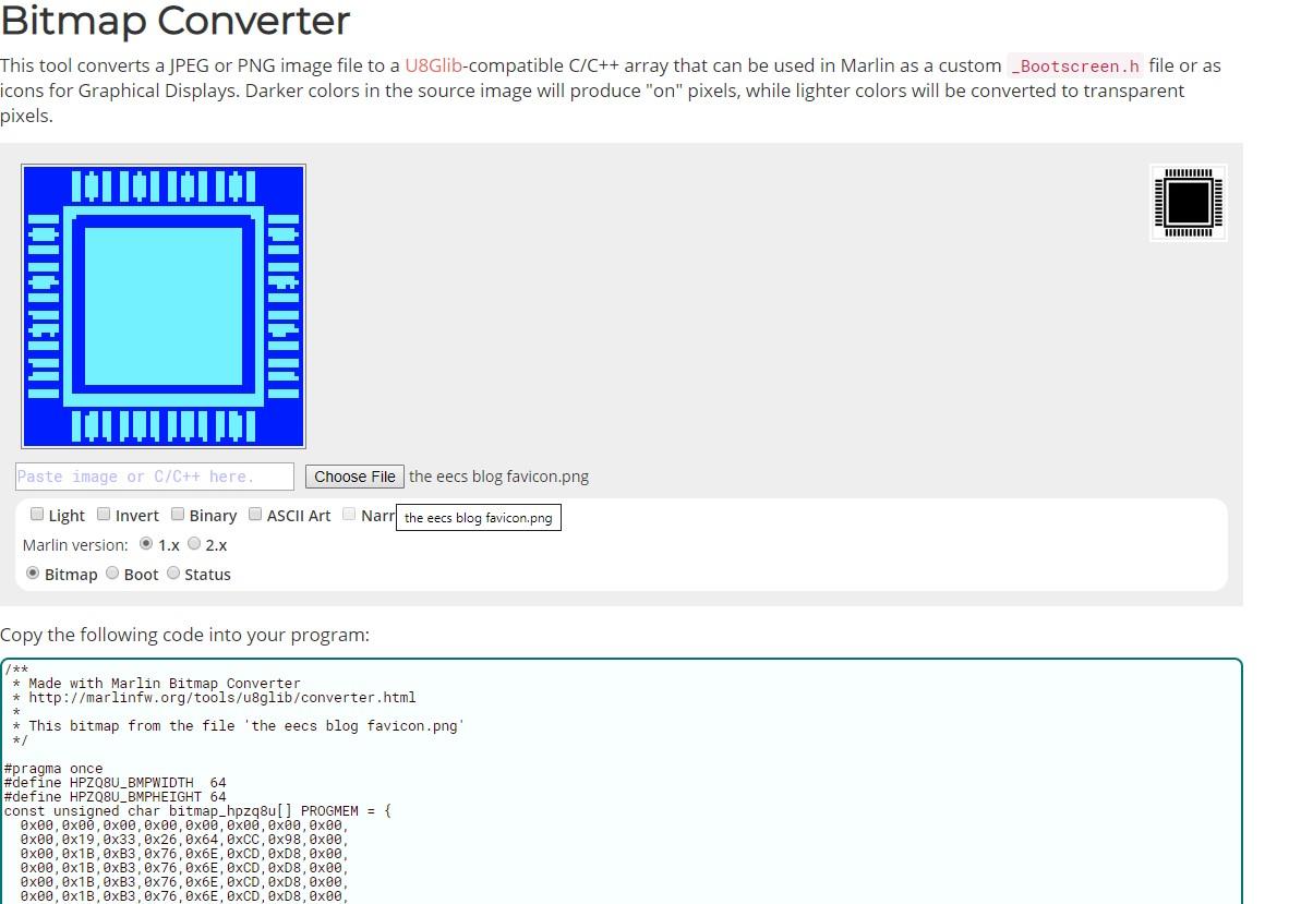
#include "myImage.h"
PROGMEM const unsigned char myImage[] = {
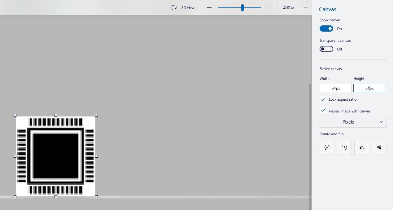
64, 64, //resolution
0x00,0x00,0x00,0x00,0x00,0x00,0x00,0x00,
0x00,0x19,0x33,0x26,0x64,0xCC,0x98,0x00,
0x00,0x1B,0xB3,0x76,0x6E,0xCD,0xD8,0x00,
0x00,0x1B,0xB3,0x76,0x6E,0xCD,0xD8,0x00,
0x00,0x1B,0xB3,0x76,0x6E,0xCD,0xD8,0x00,
0x00,0x1B,0xB3,0x76,0x6E,0xCD,0xD8,0x00,
0x00,0x1B,0xB3,0x76,0x6E,0xCD,0xD8,0x00,
0x00,0x19,0x33,0x26,0x64,0xCC,0x98,0x00,
0x00,0x00,0x00,0x00,0x00,0x00,0x00,0x00,
0x00,0x7F,0xFF,0xFF,0xFF,0xFF,0xFE,0x00,
0x00,0x7F,0xFF,0xFF,0xFF,0xFF,0xFE,0x00,
0x7F,0x70,0x00,0x00,0x00,0x00,0x0E,0xFE,
0x7F,0x60,0x00,0x00,0x00,0x00,0x06,0xFE,
0x00,0x60,0x00,0x00,0x00,0x00,0x06,0x00,
0x3E,0x63,0xFF,0xFF,0xFF,0xFF,0xC6,0xFC,
0x7F,0x63,0xFF,0xFF,0xFF,0xFF,0xC6,0xFE,
0x3E,0x63,0xFF,0xFF,0xFF,0xFF,0xC6,0x7C,
0x00,0x63,0xFF,0xFF,0xFF,0xFF,0xC6,0x00,
0x7F,0x63,0xFF,0xFF,0xFF,0xFF,0xC6,0xFE,
0x7F,0x63,0xFF,0xFF,0xFF,0xFF,0xC6,0xFE,
0x00,0x63,0xFF,0xFF,0xFF,0xFF,0xC6,0x00,
0x00,0x63,0xFF,0xFF,0xFF,0xFF,0xC6,0x00,
0x7F,0x63,0xFF,0xFF,0xFF,0xFF,0xC6,0xFE,
0x7F,0x63,0xFF,0xFF,0xFF,0xFF,0xC6,0xFE,
0x00,0x63,0xFF,0xFF,0xFF,0xFF,0xC6,0x00,
0x3E,0x63,0xFF,0xFF,0xFF,0xFF,0xC6,0xFC,
0x7F,0x63,0xFF,0xFF,0xFF,0xFF,0xC6,0xFE,
0x3C,0x63,0xFF,0xFF,0xFF,0xFF,0xC6,0x34,
0x00,0x63,0xFF,0xFF,0xFF,0xFF,0xC6,0x00,
0x7F,0x63,0xFF,0xFF,0xFF,0xFF,0xC6,0xFE,
0x7F,0x63,0xFF,0xFF,0xFF,0xFF,0xC6,0xFE,
0x00,0x63,0xFF,0xFF,0xFF,0xFF,0xC6,0x00,
0x00,0x63,0xFF,0xFF,0xFF,0xFF,0xC6,0x00,
0x7F,0x63,0xFF,0xFF,0xFF,0xFF,0xC6,0xFE,
0x3F,0x63,0xFF,0xFF,0xFF,0xFF,0xC6,0xFE,
0x00,0x63,0xFF,0xFF,0xFF,0xFF,0xC6,0x00,
0x3F,0x63,0xFF,0xFF,0xFF,0xFF,0xC6,0xFC,
0x7F,0x63,0xFF,0xFF,0xFF,0xFF,0xC6,0xFE,
0x32,0x63,0xFF,0xFF,0xFF,0xFF,0xC6,0x70,
0x00,0x63,0xFF,0xFF,0xFF,0xFF,0xC6,0x00,
0x7F,0x63,0xFF,0xFF,0xFF,0xFF,0xC6,0xFE,
0x7F,0x63,0xFF,0xFF,0xFF,0xFF,0xC6,0xFE,
0x00,0x63,0xFF,0xFF,0xFF,0xFF,0xC6,0x00,
0x00,0x63,0xFF,0xFF,0xFF,0xFF,0xC6,0x00,
0x7F,0x63,0xFF,0xFF,0xFF,0xFF,0xC6,0xFE,
0x3F,0x63,0xFF,0xFF,0xFF,0xFF,0xC6,0xFE,
0x00,0x63,0xFF,0xFF,0xFF,0xFF,0xC6,0x00,
0x3F,0x63,0xFF,0xFF,0xFF,0xFF,0xC6,0xFC,
0x7F,0x63,0xFF,0xFF,0xFF,0xFF,0xC6,0xFE,
0x00,0x63,0xFF,0xFF,0xFF,0xFF,0xC6,0x00,
0x00,0x60,0x00,0x00,0x00,0x00,0x06,0x00,
0x7F,0x60,0x00,0x00,0x00,0x00,0x06,0xFE,
0x7F,0x7F,0xFF,0xFF,0xFF,0xFF,0xFE,0xFE,
0x00,0x7F,0xFF,0xFF,0xFF,0xFF,0xFE,0x00,
0x00,0x7F,0xFF,0xFF,0xFF,0xFF,0xFE,0x00,
0x00,0x00,0x00,0x00,0x00,0x00,0x00,0x00,
0x00,0x19,0xB3,0x76,0x6E,0xCD,0x98,0x00,
0x00,0x1B,0xB3,0x76,0x6E,0xCD,0xD8,0x00,
0x00,0x1B,0xB3,0x76,0x6E,0xCD,0xD8,0x00,
0x00,0x1B,0xB3,0x76,0x6E,0xCD,0xD8,0x00,
0x00,0x1B,0xB3,0x76,0x6E,0xCD,0xD8,0x00,
0x00,0x1B,0xB3,0x76,0x6E,0xCD,0xD8,0x00,
0x00,0x19,0x12,0x22,0x44,0x48,0x98,0x00,
0x00,0x00,0x00,0x00,0x00,0x00,0x00,0x00
};