About
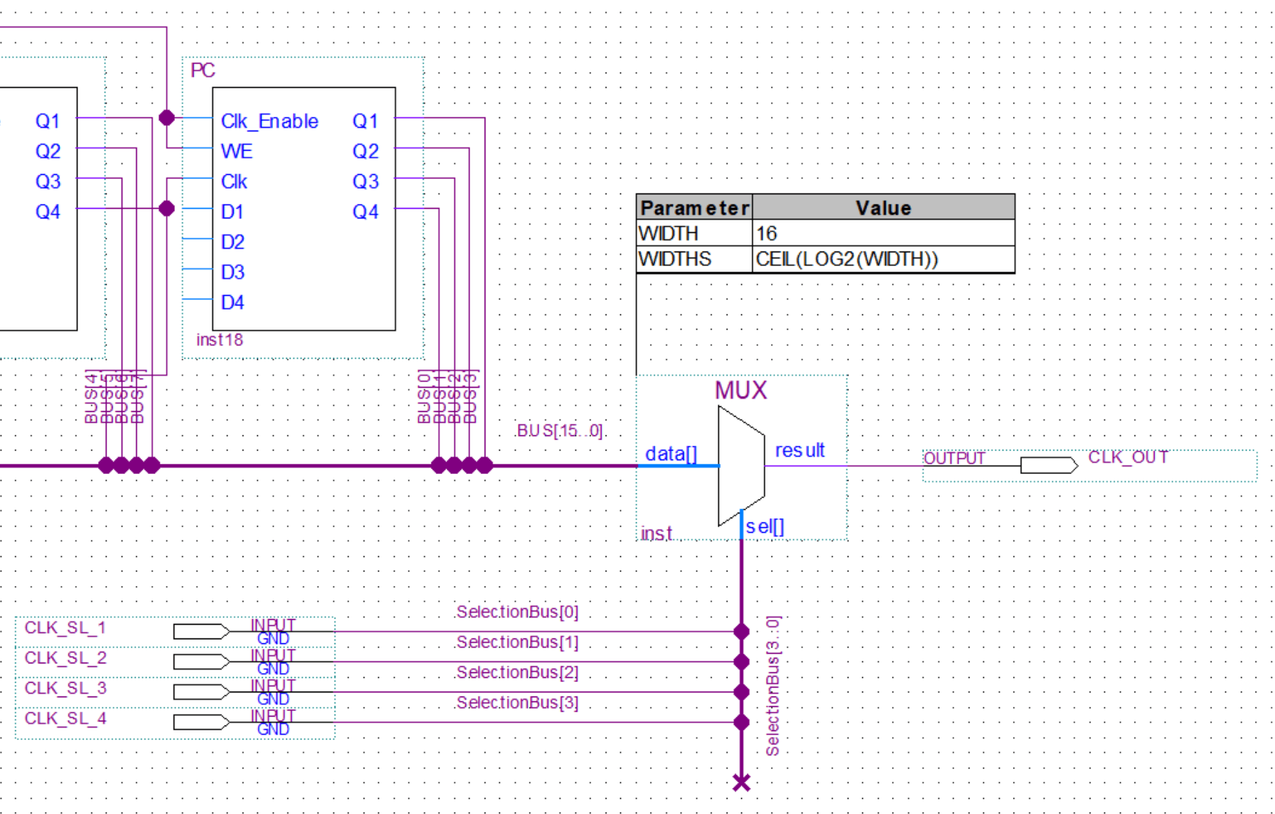
In this post, we’ll take a look at multiplexers and demultiplexers. In my 8-bit computer build, I only used multiplexers, you can see them being used in the clock generation circuits. I will however still cover demultiplexers in this post for the sake of completeness.
Multiplexers are used to select one of the multiple inputs and output it to one common output. Demultiplexers do the opposite of that and take in one input and put it out through one of the multiple outputs that was selected.
Let’s just take a look at the brief explanations and schematic bellow for a better understanding.
Multiplexer
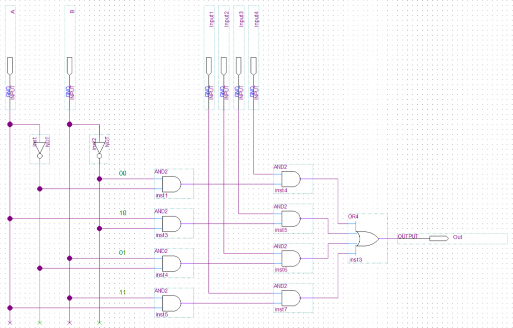
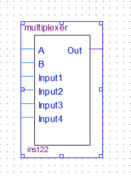
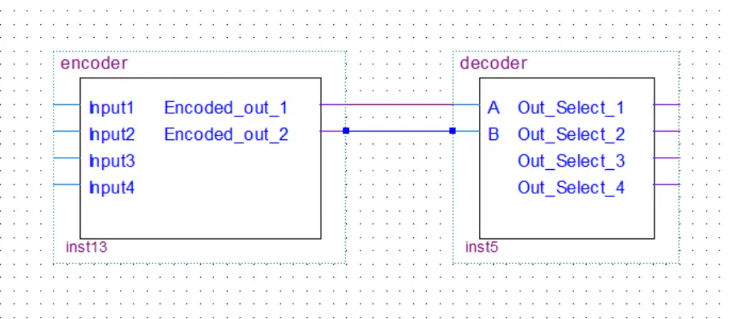
The first part of the multiplexer is a decoder(see more about decoders in this post). It will take the binary input and decode it to one output. Then each one of the decoder outputs is feed into an AND gate together with one of the inputs. In the end, all the outputs of the AND gates get feed into an OR gate with multiple inputs.
Truth Table
| A | B | Out |
|---|---|---|
| 0 | 0 | Input1 => Out |
| 1 | 0 | Input2 => Out |
| 0 | 1 | Input3 => Out |
| 1 | 1 | Input4 => Out |
Boolean Expression
Demultiplexer
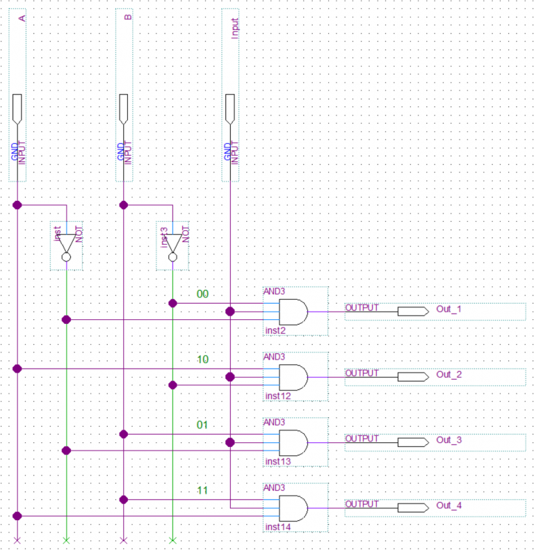
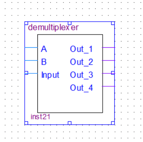
The demultiplexer is basically just a decoder(see more about decoders in this post). It will take the binary input and decode it to one output. Compared to a regular decoder the demultiplexer also takes the data input line and conects to the input of every AND gate in the decoder.
Truth Table
| A | B | Out |
|---|---|---|
| 0 | 0 | Input => Out_1 |
| 1 | 0 | Input => Out_2 |
| 0 | 1 | Input => Out_3 |
| 1 | 1 | Input => Out_4 |
Boolean Expression
Out_2 = A.B'.Input
Out_3 = A'.B.Input
Out_4 = A.B.Input
