About
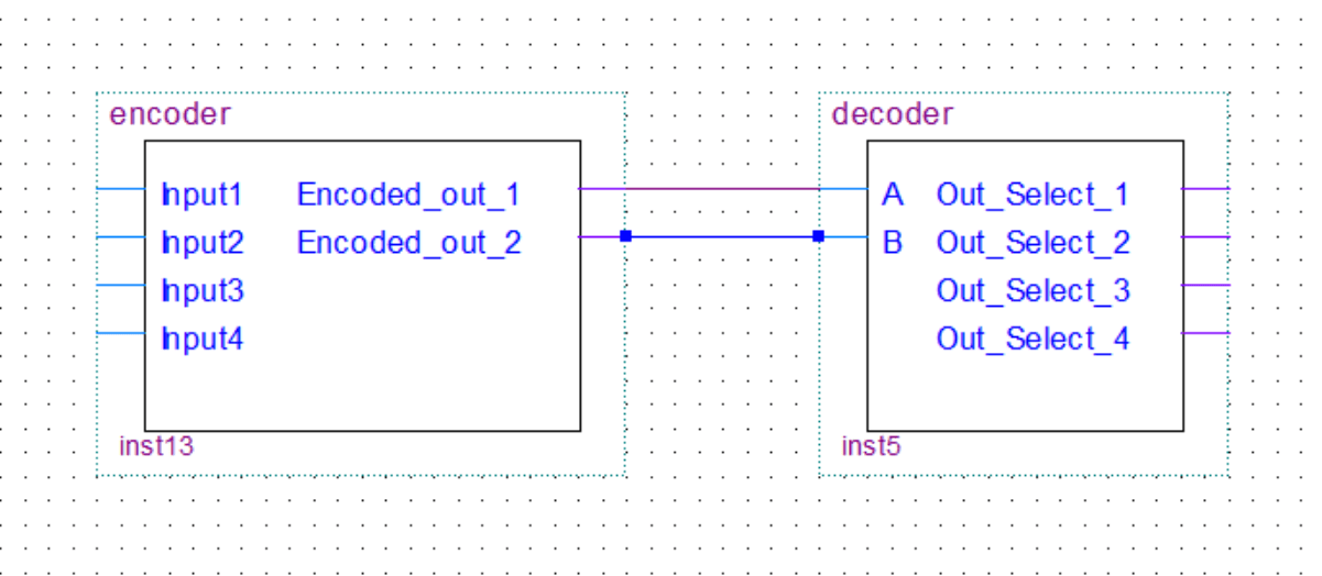
In my 8-bit computer build, I only used decoders. However, I will still cover encoders in this post for the sake of completeness. You can see the decoders being used in the RAM, multiplexers, and the control unit of the computer.
Decoders decode the binary value on the input to an individual selection on the output. The encoder will of course do the exact opposite.
In this post, we’ll take a look at encoders/decoders with 4 inputs/outputs because it’s easier to understand how they work. The logic is the same for more inputs/outputs, the logic circuit just gets scaled up.
Decoder
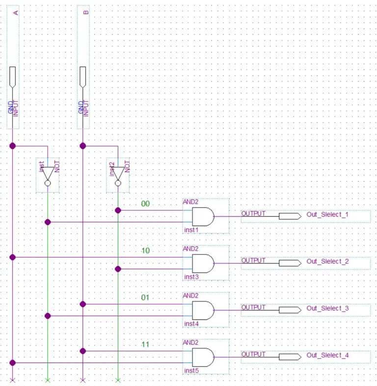
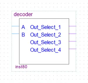
In this example, we have a 2 to 4 decoder(described as n to 2n ). The n stands for the number of input lines. This decoder will take 2 input lines in and decode(select an output by setting it high) them to 2n or in this case 4 output lines.
Truth Table
| A | B | Out_1 | Out_2 | Out_3 | Out_4 |
|---|---|---|---|---|---|
| 0 | 0 | 1 | 0 | 0 | 0 |
| 1 | 0 | 0 | 1 | 0 | 1 |
| 0 | 1 | 0 | 0 | 1 | 0 |
| 1 | 1 | 0 | 0 | 0 | 1 |
Boolean Expression
out_2 = A.B'
out_3 = A'.B
out_4 = A.B
Encoder
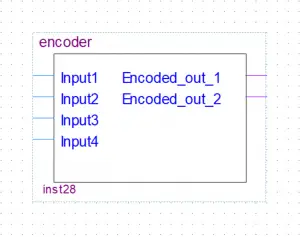
The encoder will do the opposite of the decoder. In this example, we have a 4 to 2 encoder(described as 2n to n ). The n stands for the number of output lines. This encoder will take 4 or 2n input lines in and encode them to n or in this case 2 output lines(select an output by setting it high).
Truth table
| Input4 | Input3 | Input2 | Input1 | out_2 | out_1 |
|---|---|---|---|---|---|
| 0 | 0 | 0 | 1 | 0 | 0 |
| 0 | 0 | 1 | 0 | 0 | 1 |
| 0 | 1 | 0 | 0 | 1 | 0 |
| 1 | 0 | 0 | 0 | 1 | 1 |
Boolean Expression
out_2 = Input3 + Input4
