8-Bit Computer Control Unit

control unit and microinstruction counter
Share:

About

In this post, we’ll take a look at the control unit of my 8-bit computer. Ben used an EEPROM to make the control unit in his computer. This is a quite clever approach if you are building your computer on a breadboard as it drastically decreases the complexity, amount of components and space needed. But in my case, it was much easier to just implement the control unit using discrete logic gates. 

The job of the control unit is to take in an instruction decode it and execute it by toggling the control lines to various components in the appropriate sequence. 

Note: The images don’t include the whole circuits as they are too big. The circuitry just repeats anyway so you are not missing out on anything. 

Instruction Register

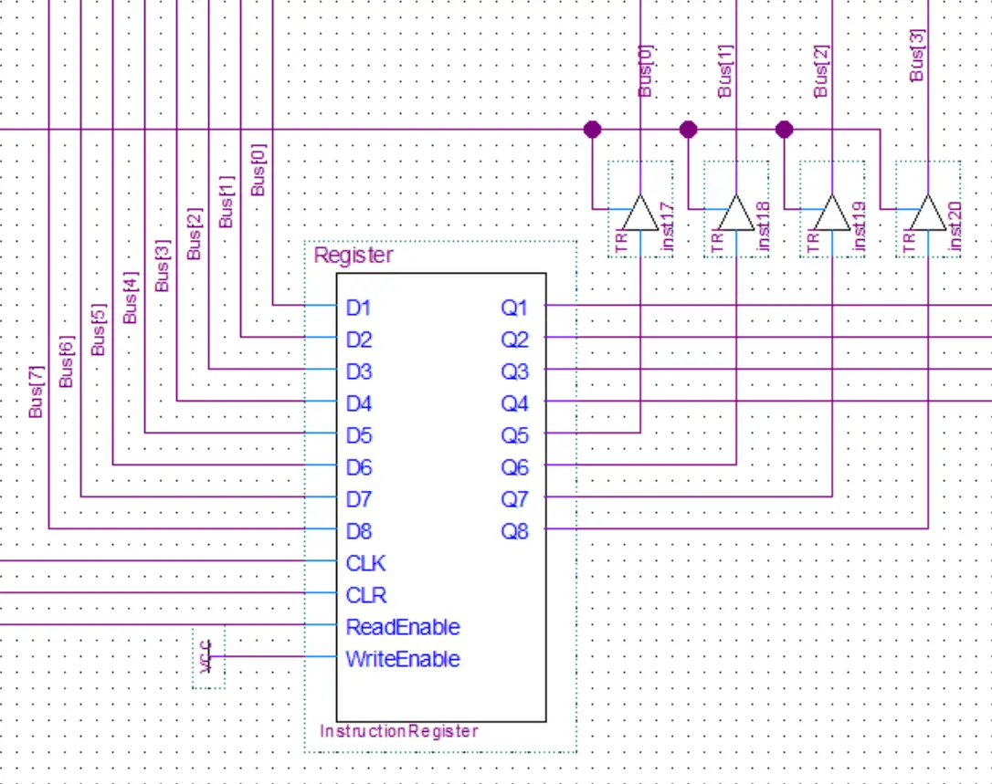
The instruction register as the name implies is used to store the current instruction and forward it to the control unit to be decoded. It will read 8 bits from the bus. Once the values have been read into the register it will output 4 of those bits (the instruction part) to the control unit to be decoded. While the other 4 bits(the value) will be output back to the bus.

Control Unit

Here you can see the inputs coming into the control unit from the instruction register, flags register, and the microinstruction counter

The microinstruction counter is just a ripple-carry counter(same as the program counter). It is used to step through all the single actions actually required to execute an instruction.

The flags register is used to store the flags conditions from the previous operation. This computer has two flags. The zero flag is for when the result of a computation in the ALU is zero. While the Carry flag is for when the computation in the ALU exceeds 255 and carries over/overflows. These flags can then be used to implement the JMC(jump if carry) and JMZ(jump if zero).

Finally, you can also see a bunch of output lines to control all the various components of the computer

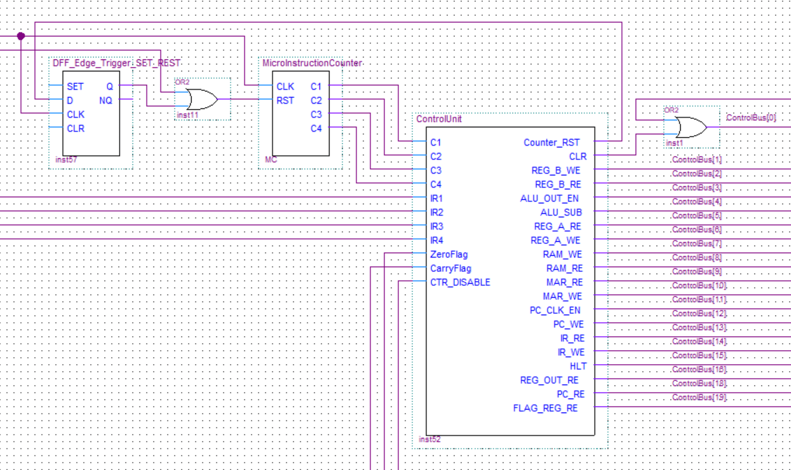
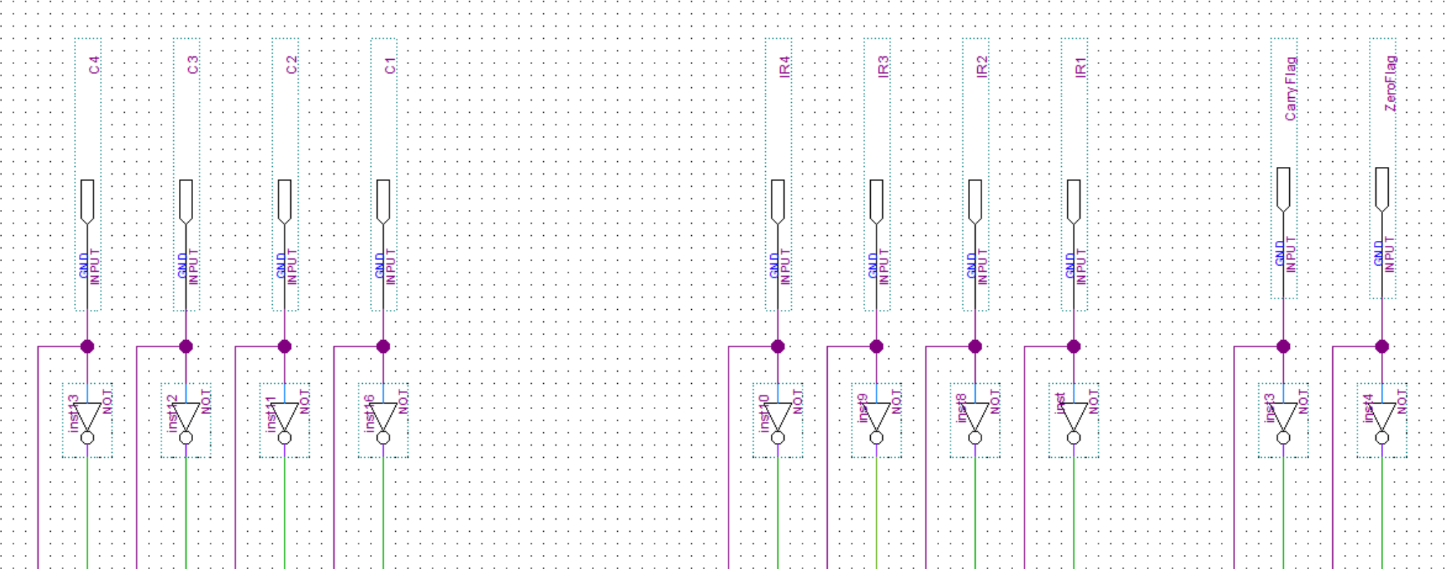
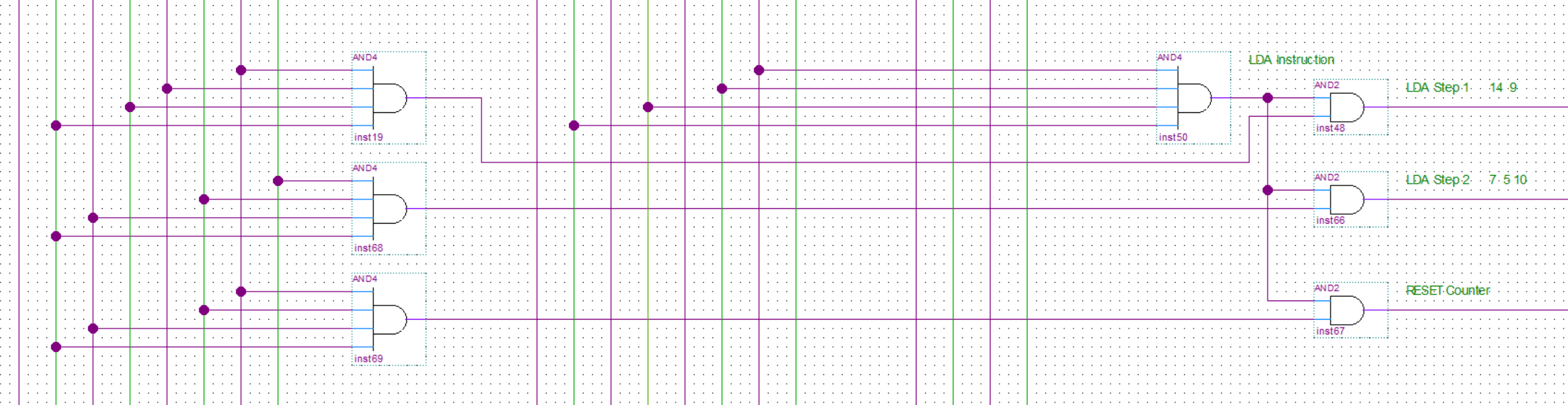
In the first image below, you can see the inputs to the decoder. After that, there are two examples of how the instructions are decoded to the multiple steps(microinstruction) required to execute them.
There are three decoders. First for selecting the instruction(input from the instruction register), second for selecting the step(input from the microinstruction counter) and the third used for the flags in case the instruction requires that like the JMZ and JMC instructions.
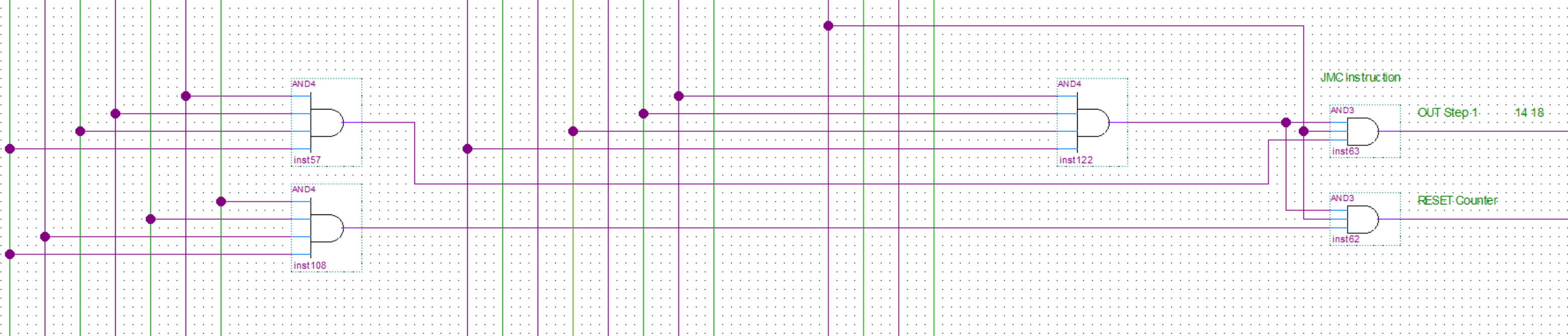
Finally, this is an example of an output. All/most of the outputs have OR gates connected to them to funnel in the signals from all the microinstruction steps that require that particular output. There is also an AND gate at the end so all the outputs can either be enabled or disabled.
Share:

Leave a Reply

Your email address will not be published. Required fields are marked *

The following GDPR rules must be read and accepted:
This form collects your name, email and content so that we can keep track of the comments placed on the website. For more info check our privacy policy where you will get more info on where, how and why we store your data.

Advertisment ad adsense adlogger