About
Simple Version
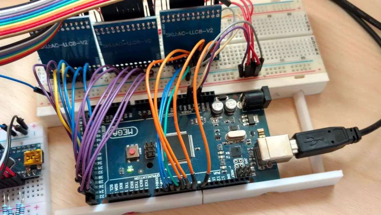
This is the first version of the programmer I made. It’s made from an Arduino nano. The limitation of this design is that you can only have a 4 bit memory address and 8 bit values(otherwise you run out of pins on the nano). The Arduino also has to be reprogrammed with every change to the machine code.
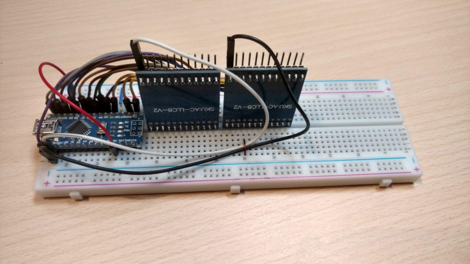
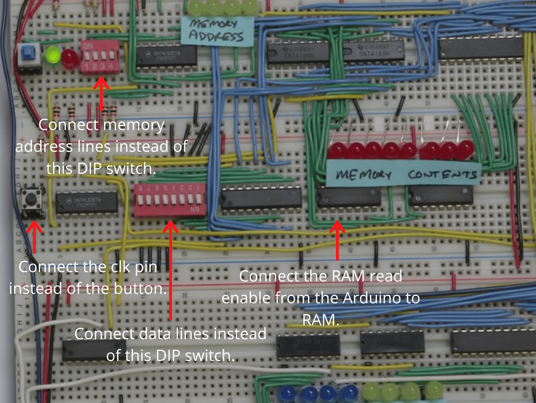
Connections to a breadboard computer:
Arduino code:
void setup() {
  //Set pins.
  pinMode(0, OUTPUT);
  pinMode(1, OUTPUT);
  pinMode(2, OUTPUT);
  pinMode(3, OUTPUT);
  pinMode(4, OUTPUT);
  pinMode(5, OUTPUT);
  pinMode(6, OUTPUT);
  pinMode(7, OUTPUT);
  pinMode(8, OUTPUT);
  pinMode(9, OUTPUT);
  pinMode(10, OUTPUT);
  pinMode(11, OUTPUT);
  pinMode(12, OUTPUT);
  pinMode(13, OUTPUT);

  //Array containing your machine code.
  int dataArray [16][12]{
        //LSB                 MSB     MEM. ADDR.
        { 1, 0, 0, 0,  0, 1, 1, 1,    0, 0, 0, 0},  //1
        { 0, 1, 0, 0,  1, 1, 1, 1,    1, 0, 0, 0},  //2
        { 1, 1, 0, 0,  0, 0, 0, 0,    0, 1, 0, 0},  //3
        { 0, 0, 1, 0,  0, 0, 0, 0,    1, 1, 0, 0},  //4
        { 0, 0, 0, 0,  0, 0, 0, 0,    0, 0, 1, 0},  //5
        { 0, 0, 0, 0,  0, 0, 0, 0,    1, 0, 1, 0},  //6
        { 0, 0, 0, 0,  0, 0, 0, 0,    0, 1, 1, 0},  //7
        { 0, 0, 0, 0,  0, 0, 0, 0,    1, 1, 1, 0},  //8
        { 0, 0, 0, 0,  0, 0, 0, 0,    0, 0, 0, 1},  //9
        { 0, 0, 0, 0,  0, 0, 0, 0,    1, 0, 0, 1},  //10
        { 0, 0, 0, 0,  0, 0, 0, 0,    0, 1, 0, 1},  //11
        { 0, 0, 0, 0,  0, 0, 0, 0,    1, 1, 0, 1},  //12
        { 0, 0, 0, 0,  0, 0, 0, 0,    0, 0, 1, 1},  //13
        { 0, 0, 0, 0,  0, 0, 0, 0,    1, 0, 1, 1},  //14
        { 0, 0, 1, 0,  0, 0, 0, 0,    0, 1, 1, 1},  //15
        { 0, 1, 0, 0,  0, 0, 0, 0,    1, 1, 1, 1},  //16
  };

  delay(1000);
  writeToRAM(dataArray);
  resetLines();
}

void loop() {

}

static void resetLines(){
  //Bus
  digitalWrite(0, LOW);
  digitalWrite(1, LOW);
  digitalWrite(2, LOW);
  digitalWrite(3, LOW);
  digitalWrite(4, LOW);
  digitalWrite(5, LOW);
  digitalWrite(6, LOW);
  digitalWrite(7, LOW);

  //RAM Adress
  digitalWrite(8, LOW);
  digitalWrite(9, LOW);
  digitalWrite(10, LOW);
  digitalWrite(11, LOW);

  //CLK
  digitalWrite(12, LOW);

  //RAM RE
  digitalWrite(13, LOW);
}

static void writeToRAM(int dataArray [16][12] ){
  //Iterate through the machine code array and toggle the appropriate pins.
  for(int i = 0; i < 16; i++){
      //Bus
      digitalWrite(0, getState(dataArray[i][0]));
      digitalWrite(1, getState(dataArray[i][1]));
      digitalWrite(2, getState(dataArray[i][2]));
      digitalWrite(3, getState(dataArray[i][3]));
      digitalWrite(4, getState(dataArray[i][4]));
      digitalWrite(5, getState(dataArray[i][5]));
      digitalWrite(6, getState(dataArray[i][6]));
      digitalWrite(7, getState(dataArray[i][7]));

      //RAM Adress
      digitalWrite(8, getState(dataArray[i][8]));
      digitalWrite(9, getState(dataArray[i][9]));
      digitalWrite(10, getState(dataArray[i][10]));
      digitalWrite(11, getState(dataArray[i][11]));


      //RAM RE
      digitalWrite(13, HIGH);
      delay(10);

      //Delay clock so the data can get to the destination before the rising edge of the clock.
      //delay(100);

      //CLK
      digitalWrite(12, HIGH);
      delay(100);
      digitalWrite(12, LOW);
      delay(10);

      //RAM RE
      digitalWrite(13, LOW);

      //Delay before next program cycle.
      delay(100);
  }
}

static bool getState(int bitValue){
    if(bitValue == 0){
      return false;
    }else{
      return true;
    }
}
From the Arduino sketch you can see that pins 0-7 are data lines, 8-11 are memory address lines, 12 is RAM read enable and 13 is the clock.
To program you computer you first need to write your program in machine code. Then you enter your machine code into the dataArray. The first 8 numbers are the memory content while the last 4 are the memory address. After you do that you have to flash the sketch to the Arduino.
Finally, you can just use the reset button on the Arduino to initiate the programming process as when the Arduino resets the program will execute.
After the computer has been programmed the Arduino programmer has to be disconnected or turned off as otherwise it will pull down the data lines. This can also be avoided if you connect the Arduino to your RAM through OR gates(this is what I did with my computer).
Programmer with an "IDE"
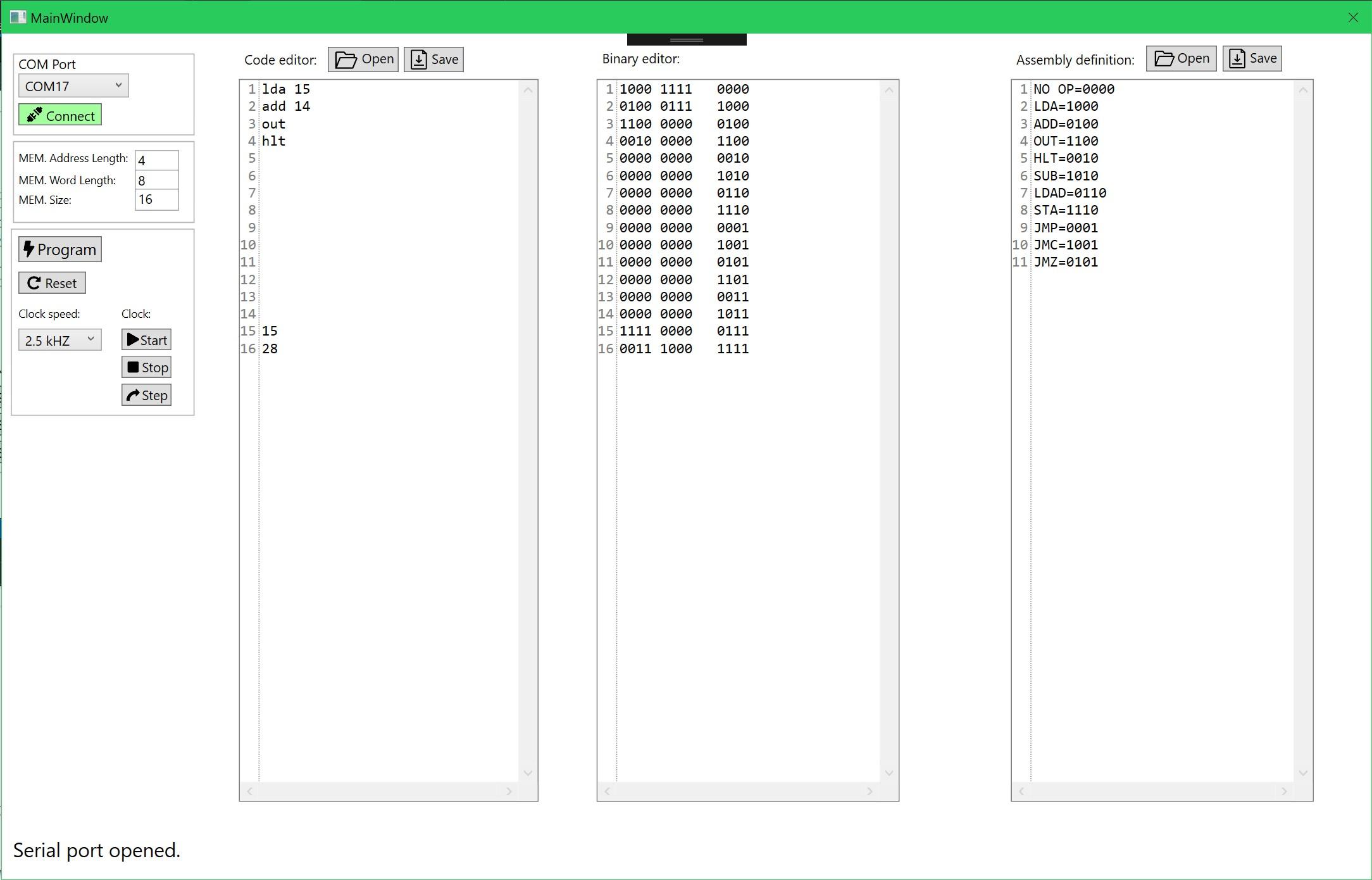
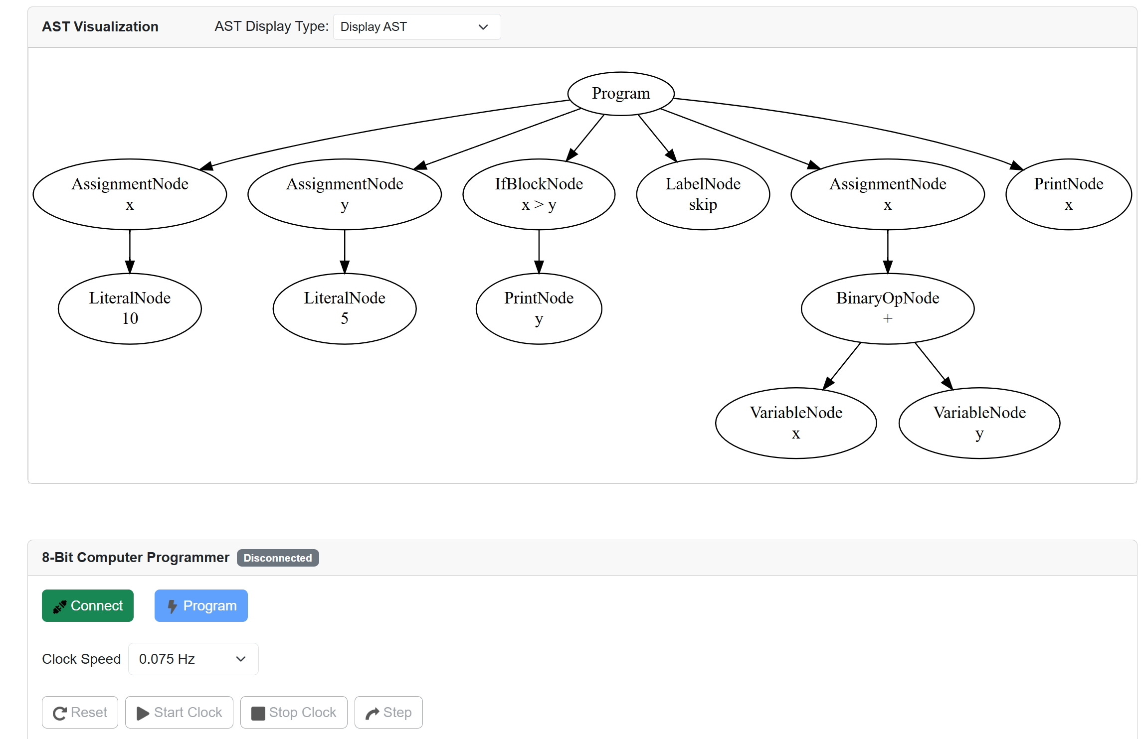
To make programming the 8-bit computer even easier I decided to make a simple sort of an IDE that can connect to the Arduino programmer and program the computer through it without having to reflash it with every change of the program.
The IDE has three code editors. The last window has the assembly definition where you map your custom machine code for the specific computer you made to your specific custom assembly language you made. Then you can write an assembly program in the first code editor. The machine code will automatically get generated in the middle editor.
On the left, you have the controls column. At the very top, you can establish a COM port connection to the Arduino.
Then you have the option to set your RAM size, RAM word length, and the memory address length. Currently, this is fixed and can’t be changed. I didn’t really need the option for a bigger memory so I skipped implementing this feature(might add it in the future).
Update:
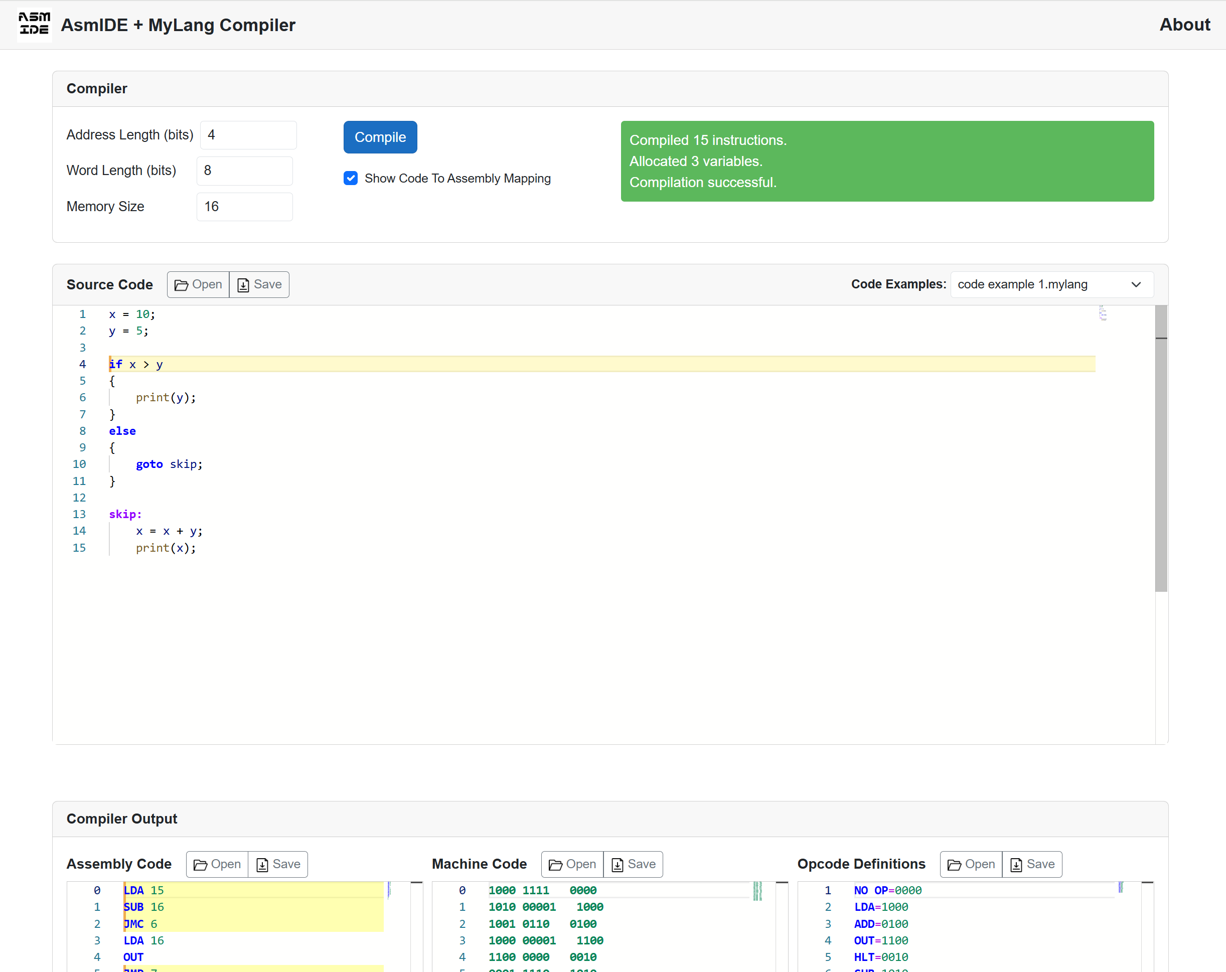
I have ported AsmIDE into a Blazor web app, including a custom compiler I made. For a while, I wanted to make my own compiler for fun and learning. Initially, I was going to make a C compiler, but then I thought it would be nice if I actually made a simple compiler for the 8-bit computer I made.
You can access the web app here: AsmIDE + MyLang Compiler
See more about the compiler itself in this blog post here.
Arduino Code:
const byte numChars = 27;
char receivedChars[numChars];
int memData[16][12];
byte memCounter = 0;
boolean newData = false;
boolean dataStart = false;

//Pin assignments///////////////
const byte strtClkPin = 36;
const byte stopClkPin = 37;
const byte rsetPin = 2;
const byte progEnPin = 3;
const byte clkStpPin = 4;
const byte clkSetPin1 = 5;
const byte clkSetPin2 = 6;
const byte clkSetPin3 = 7;
const byte clkSetPin4 = 8;
////////////////////////////////

void setup() {
  setPinModes();
  Serial.begin(115200);

  digitalWrite(progEnPin, LOW);
  stopClock();
  resetDevice();
  digitalWrite(clkSetPin1, LOW);
  digitalWrite(clkSetPin2, LOW);
  digitalWrite(clkSetPin3, LOW);
  digitalWrite(clkSetPin4, LOW);
}

void loop() {
    rxData();
    rxMemDataEnd();
}

void rxData() {
    static byte count = 0;
    char ch;

  //Check if serial data is available.
    while(Serial.available() > 0 && newData == false) {
        //Read and remove character from the serial buffer.
        ch = Serial.read();

        //Check if it's the start of the data.
        if(ch == '_'){
          dataStart = true;
        }

        if(dataStart && ch != '_'){
          if(ch != '\n'){
              receivedChars[count] = ch;
              count++;
              if(count >= numChars){
                  count = numChars - 1;
              }
          }
          else{
              //Terminate string.
              receivedChars[count] = '\0';

              char command[5];

              getCommand(command);

              if(strcmp(command, "prog") == 0){
                getMemData();
              }else if(strcmp(command, "strt") == 0){
                startClock();
                Serial.print("strt done");
              }else if(strcmp(command, "stop") == 0){
                stopClock();
                Serial.print("stop done");
              }else if(strcmp(command, "step") == 0){
                clockStep();
                Serial.print("step done");
              }else if(strcmp(command, "rset") == 0){
                resetDevice();
                Serial.print("rset done");
              }else if(strcmp(command, "clks") == 0){
                setClockSpeed();
                Serial.print("clks done");
              }else if(strcmp(command, "prst") == 0){
                programmerReset();
                Serial.print("prst done");
              }else{
                Serial.print("Bad command!");
              }

              count = 0;
              newData = true;
              dataStart = false;
            }
       }
    }
}

static void programmerReset(){
  //Reset variables.
  memCounter = 0;
  newData = false;
  dataStart = false;

  //Empty serial buffer.
  while(Serial.available() > 0){
    Serial.read();
  }
}

//Currently not used.
static void getInfo(int *memInfo){
  char memAddressLengthStr[3];
  char memLocationLengthStr[3];
  char memLocationCountStr[6];

  for(int i = 4; i <= 12; i++){
    if(i <= 5){
      memAddressLengthStr[i-4] = receivedChars[i];
      if(i-4 == 1){
        memAddressLengthStr[i-3] = '\0';
      }
    }else if(i <= 7){
      memLocationLengthStr[i-6] =  receivedChars[i];
      if(i-6 == 1){
        memLocationLengthStr[i-5] = '\0';
      }
    }else if(i <= 12){
      memLocationCountStr[i-8] =  receivedChars[i];

      if(i-11 == 1){
        memLocationCountStr[i-7] = '\0';
      }
    }
  }

  //Convert char to
  memInfo[0] = atoi(memAddressLengthStr);
  memInfo[1] = atoi(memLocationLengthStr);
  memInfo[2] = atoi(memLocationCountStr);

}

static void getClockSpeed(int *clkSpeedValues){
  for(int i = 4; i <= 7; i++){
    clkSpeedValues[i-4] = (receivedChars[i] - '0');
  }
}

static void setClockSpeed(){
  int clkSpeedValues[4];

  getClockSpeed(clkSpeedValues);

  digitalWrite(clkSetPin1, getState(clkSpeedValues[0]));
  digitalWrite(clkSetPin2, getState(clkSpeedValues[1]));
  digitalWrite(clkSetPin3, getState(clkSpeedValues[2]));
  digitalWrite(clkSetPin4, getState(clkSpeedValues[3]));
}

static void setPinModes(){
  //Data pins///////////////
  pinMode(22, OUTPUT); //LSB
  pinMode(23, OUTPUT);
  pinMode(24, OUTPUT);
  pinMode(25, OUTPUT);

  pinMode(26, OUTPUT);
  pinMode(27, OUTPUT);
  pinMode(28, OUTPUT);
  pinMode(29, OUTPUT); //MSB
  //////////////////////////

  //Mem. Add. Pins/////////
  pinMode(30, OUTPUT);
  pinMode(31, OUTPUT);
  pinMode(32, OUTPUT);
  pinMode(33, OUTPUT);
  /////////////////////////

  //Clk
  pinMode(34, OUTPUT);
  //RAM read enable
  pinMode(35, OUTPUT);

  //Start
  pinMode(strtClkPin, OUTPUT);
  //Stop
  pinMode(stopClkPin, OUTPUT);

  //Clear
  pinMode(rsetPin, OUTPUT);
  //Program enable
  pinMode(progEnPin, OUTPUT);
  //Step
  pinMode(clkStpPin, OUTPUT);

  //Clk speed selection//
  pinMode(clkSetPin1, OUTPUT);
  pinMode(clkSetPin2, OUTPUT);
  pinMode(clkSetPin3, OUTPUT);
  pinMode(clkSetPin4, OUTPUT);
  ///////////////////////
}

static void getMemData(){
  for(int i = 0; i <= 11 ; i++){
    memData[memCounter][i] = (receivedChars[i+13] - '0');
  }

  //Next mem. position.
  memCounter++;
}

static void getCommand(char *command){
  for(int i = 0; i <= 3; i++){
    command[i] = receivedChars[i];
  }

  //Terminate string.
  command[4] = '\0';
}

static void rxMemDataEnd(){
    //If new data is available.
    if(newData == true){
      //Check if data transfer is over.
      if(memCounter == 16){
        writeToRAM();

        //Reset.
        memCounter = 0;

        Serial.print("prog done");
      }else{
        //Signal that the data was read.
        Serial.print("ok");
      }

      //Reset.
      newData = false;
      delay(10);
    }
}

static void clockStep(){
  digitalWrite(clkStpPin, HIGH);
  delay(50);
  digitalWrite(clkStpPin, LOW);
}

static void resetDevice(){
  digitalWrite(rsetPin, HIGH);
  delay(50);
  digitalWrite(rsetPin, LOW);
}

static void startClock(){
  digitalWrite(strtClkPin, HIGH);
  delay(50);
  digitalWrite(strtClkPin, LOW);
}

static void stopClock(){
  digitalWrite(stopClkPin, HIGH);
  delay(50);
  digitalWrite(stopClkPin, LOW);
}

static void writeToRAM(){
  stopClock();
  resetDevice();
  digitalWrite(progEnPin, HIGH);
  delay(10);

  //Iterate through the machine code array and toggle the appropriate pins.
  for(int i = 0; i < 16; i++){
      //Bus
      digitalWrite(22, getState(memData[i][0]));
      digitalWrite(23, getState(memData[i][1]));
      digitalWrite(24, getState(memData[i][2]));
      digitalWrite(25, getState(memData[i][3]));
      digitalWrite(26, getState(memData[i][4]));
      digitalWrite(27, getState(memData[i][5]));
      digitalWrite(28, getState(memData[i][6]));
      digitalWrite(29, getState(memData[i][7]));

      //RAM Adress
      digitalWrite(30, getState(memData[i][8]));
      digitalWrite(31, getState(memData[i][9]));
      digitalWrite(32, getState(memData[i][10]));
      digitalWrite(33, getState(memData[i][11]));


      //RAM RE
      digitalWrite(35, HIGH);
      delay(10);

      //Delay clock so the data can get to the destination before the rising edge of the clock.
      //delay(100);

      //CLK
      digitalWrite(34, HIGH);
      delay(10);
      digitalWrite(34, LOW);
      delay(10);

      //RAM RE
      digitalWrite(35, LOW);

      //Delay before next program cycle.
      delay(10);
  }

  //PROG EN
  digitalWrite(progEnPin, LOW);
}

static bool getState(int bitValue){
    if(bitValue == 0){
      return false;
    }else if(bitValue == 1){
      return true;
    }
}
Here I will briefly describe how the code works(for more detail see the code and the comments).
The Arduino receives the values over the serial port from the App. First, it determines what command it has just received. After that, it will execute the appropriate action like start, stop, program, … The machine code data arrives to the Arduino in chunks(each mem. address is one chunk) and is then stored in an array. This keeps happening until the last chunk of data has been received. Finally, the processes to shift all the values from the array into the 8-bit computers RAM begins. This is done by toggling the IO pins high/low depending on the values in the array.
I know that storing the values in the Arduino isn’t the best solution. Ideally, the data should just be immediately written into the computers RAM without being buffer in an array. The reason things work the way they do is that I just upgraded the code from the simple version of the programmer. So if there is a need for it I might update the programmer and IDE in the future.


