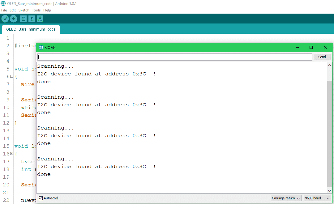
This is an I2C address scanner. It will tell you the addresses of all connected devices. What this code essentially does is it goes through all the addresses and sends a message to each one. If it gets a response from it the address will be sent over the serial port.
// --------------------------------------
// i2c_scanner
//
// Version 1
// This program (or code that looks like it)
// can be found in many places.
// For example on the Arduino.cc forum.
// The original author is not know.
// Version 2, Juni 2012, Using Arduino 1.0.1
// Adapted to be as simple as possible by Arduino.cc user Krodal
// Version 3, Feb 26 2013
// V3 by louarnold
// Version 4, March 3, 2013, Using Arduino 1.0.3
// by Arduino.cc user Krodal.
// Changes by louarnold removed.
// Scanning addresses changed from 0...127 to 1...119,
// according to the i2c scanner by Nick Gammon
// http://www.gammon.com.au/forum/?id=10896
// Version 5, March 28, 2013
// As version 4, but address scans now to 127.
// A sensor seems to use address 120.
// Version 6, November 27, 2015.
// Added waiting for the Leonardo serial communication.
//
//
// This sketch tests the standard 7-bit addresses
// Devices with higher bit address might not be seen properly.
//

#include <Wire.h>

void setup()
{
    Wire.begin();

    Serial.begin(9600);
    while (!Serial); // Leonardo: wait for serial monitor
    Serial.println("\nI2C Scanner");
}

void loop()
{
    byte error, address;
    int nDevices;

    Serial.println("Scanning...");

    nDevices = 0;
    for (address = 1; address < 127; address++) {
        // The i2c_scanner uses the return value of
        // the Write.endTransmisstion to see if
        // a device did acknowledge to the address.
        Wire.beginTransmission(address);
        error = Wire.endTransmission();

        if (error == 0) {
            Serial.print("I2C device found at address 0x");
            if (address < 16)
                Serial.print("0");
            Serial.print(address, HEX);
            Serial.println(" !");

            nDevices++;
        }
        else if (error == 4) {
            Serial.print("Unknown error at address 0x");
            if (address < 16)
                Serial.print("0");
            Serial.println(address, HEX);
        }
    }
    if (nDevices == 0)
        Serial.println("No I2C devices found\n");
    else
        Serial.println("done\n");

    delay(5000); // wait 5 seconds for next scan
}
Open the serial monitor(ctrl+shift+m), select the COM port of your device and select the baud rate that was specified in the code(9600).
You should now be seeing the I2C addresses of all present devices.
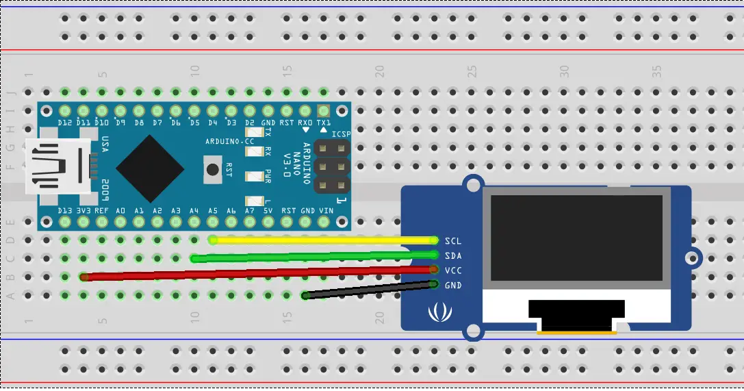
Now take the address and put it in as an input parameter of the display initialization function like so: display.begin(SSD1306_SWITCHCAPVCC, 0x3C);
Code
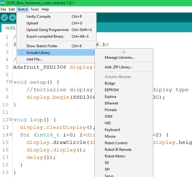
Here is the bare minimum code to make the display work and write out some text. If you need more examples for such things as drawing shapes check out the examples provided in the Arduino IDE. You can find them under: File > Examples > Adafruit SSD1306.
//Include library
#include <Adafruit_GFX.h>
#include <Adafruit_SSD1306.h>
#define OLED_RESET 4
Adafruit_SSD1306 display(OLED_RESET);
void setup()
{
//Initialize display by providing the display type and its I2C address.
display.begin(SSD1306_SWITCHCAPVCC, 0x3C);
//Set the text size and color.
display.setTextSize(1);
display.setTextColor(WHITE);
}
void loop()
{
//Clear previous image.
display.clearDisplay();
display.setCursor(0, 15);
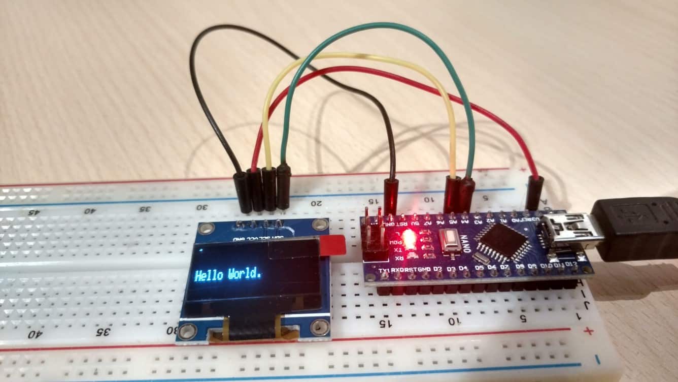
display.print("Hello World.");
//Display changes if any were made.
display.display();
delay(1);
}
Hello World!
Upload the above-provided code and you should have a Hello World.
Hi. Struggling with code to measure and display velocity using an OLED 128×32 . Works fine most of the time, but I frequently experience a RESET of my nano. This also occurs with my Uno, and also occurs when powered thru USB or 9v battery.
I am not aware of any software issues that can trigger a hard reset. Any suggestions would be most helpful. Thanks.
You say you are trying to display velocity. Do you have some extra hardware(GPS, accelerometer, …) connected to the Arduino? If so try disconnecting it and see if the resetting keeps happening.
Thank you. I’m using a contact wiper on a wheel. The contact is debounced with an RC circuit, as well as using delay(ms). The reset does not occur when the car (HO guards van) is not moving. I’ve tried using interrupts as well as digitalRead to register the contact (I do not use delay() when using the ISR.), but reset occurs regardless.
If you have an oscilloscope you should try to measure the voltage on the power rail and the input signal during the operation. Also, I would have to see your code to be able to help you any further.
Thanks. I picked up electronics/arduino in quarantine and I am using this for my remote control to my robot rover to display a bunch of stuff like temp and i.r codes. I just received my bi direction logic level converter and my next screen to get working is a 240×320 TFT SPI display for the camera system. i do have my 4 motors for 4 wheel drive up and running from a joystick however I don’t’ have the wireless working yet. hehe
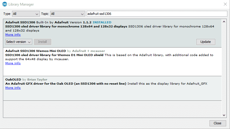
ssd1306_128x32_i2c:21:10: fatal error: Adafruit_GFX.h: No such file or directory
help me !
Multiple libraries were found for “Adafruit_GFX.h”
compilation terminated.
Used: C:\Users\avphu\OneDrive\Tài liệu\Arduino\libraries\Adafruit_GFX_Library
Not used: C:\Users\avphu\OneDrive\Tài liệu\Arduino\libraries\Adafruit-GFX-Library-master
exit status 1
Adafruit_GFX.h: No such file or directory
Me interesa hacer funcionar de esta manera básica y sin mucho artilugio, la pantalla oled 128×64 con el esp8266_01.
Ya lo hice con el esp8266 12_E (V2 y V3).
I used google translate to translate your comment. So if I understood you correctly you want to do this using the ESP8266(first version the one with 8 pins). I have never done this with the ESP8266-01, but it should be possible. The OLED screen also runs on 3.3V, so a single voltage supply can be used for both the screen and the ESP. The ESP8266-01 only has two GPIOs (GPIO0 and GPIO2).
You would have to use these two pins for the I2C communication. I think the connection would be like this: GPIO0 -> SDA and GPIO2 -> SCL
As for the software I think you need to add this library: #include <Wire.h>
And this code in the void setup:
Wire.pins(0, 2);
Wire.begin(0, 2);
I am glad my tutorial helped you. And thank you very much for pointing out the missing includes. The problem is the < and > characters sometimes get recognized as an HTML tag and that can cause problems.


Ooops – Jack Child
Hi. Struggling with code to measure and display velocity using an OLED 128×32 . Works fine most of the time, but I frequently experience a RESET of my nano. This also occurs with my Uno, and also occurs when powered thru USB or 9v battery.
I am not aware of any software issues that can trigger a hard reset. Any suggestions would be most helpful. Thanks.
You say you are trying to display velocity. Do you have some extra hardware(GPS, accelerometer, …) connected to the Arduino? If so try disconnecting it and see if the resetting keeps happening.
Thank you. I’m using a contact wiper on a wheel. The contact is debounced with an RC circuit, as well as using delay(ms). The reset does not occur when the car (HO guards van) is not moving. I’ve tried using interrupts as well as digitalRead to register the contact (I do not use delay() when using the ISR.), but reset occurs regardless.
If you have an oscilloscope you should try to measure the voltage on the power rail and the input signal during the operation. Also, I would have to see your code to be able to help you any further.
Thanks Tsla. Good tip re the power rail – the RC debounce circuit was causing the reset when the capacitor was engaged.
finally. a bare minimum. I have it working.
I am glad to hear my tutorial helped you 🙂.
Thanks. I picked up electronics/arduino in quarantine and I am using this for my remote control to my robot rover to display a bunch of stuff like temp and i.r codes. I just received my bi direction logic level converter and my next screen to get working is a 240×320 TFT SPI display for the camera system. i do have my 4 motors for 4 wheel drive up and running from a joystick however I don’t’ have the wireless working yet. hehe
ssd1306_128x32_i2c:21:10: fatal error: Adafruit_GFX.h: No such file or directory
help me !
Multiple libraries were found for “Adafruit_GFX.h”
compilation terminated.
Used: C:\Users\avphu\OneDrive\Tài liệu\Arduino\libraries\Adafruit_GFX_Library
Not used: C:\Users\avphu\OneDrive\Tài liệu\Arduino\libraries\Adafruit-GFX-Library-master
exit status 1
Adafruit_GFX.h: No such file or directory
Try renaming the “Adafruit-GFX-Library-master” folder to Adafruit_GFX_Library.
Thank you! This got me started!!!
Glad to hear that.
Me interesa hacer funcionar de esta manera básica y sin mucho artilugio, la pantalla oled 128×64 con el esp8266_01.
Ya lo hice con el esp8266 12_E (V2 y V3).
I used google translate to translate your comment. So if I understood you correctly you want to do this using the ESP8266(first version the one with 8 pins). I have never done this with the ESP8266-01, but it should be possible. The OLED screen also runs on 3.3V, so a single voltage supply can be used for both the screen and the ESP. The ESP8266-01 only has two GPIOs (GPIO0 and GPIO2).
You would have to use these two pins for the I2C communication. I think the connection would be like this: GPIO0 -> SDA and GPIO2 -> SCL
As for the software I think you need to add this library: #include <Wire.h>
And this code in the void setup:
Wire.pins(0, 2);
Wire.begin(0, 2);
Thanks, this helped me get started!
Just a heads up, the includes are missing in your examples.
I am glad my tutorial helped you. And thank you very much for pointing out the missing includes. The problem is the < and > characters sometimes get recognized as an HTML tag and that can cause problems.