In this post, we’ll take a look at the program counter of my 8-bit computer. The PC(program counter) is used to store the memory address of the next instruction to be executed. After the instruction was executed it the value in the PC will be incremented by one, therefore, pointing at the next memory address that contains the next instruction.
The PC is almost identical in construction to the microinstruction counter as both of them are just ripple-carry counters.
Differences:
The PC has the ability to read in a value as opposed to just being able to increment the existing one. This is what enables the JMP instruction.
The PC has tristate buffers to control the outputs(because it is connected straight to the bus). Meanwhile, the microinstruction counter is always outputting its value.
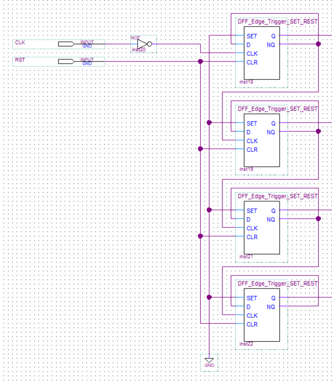
Note: A ripple-carry counter is an asynchronous counter because only the first flip-flop is connected to the clock. All others will receive their clock signals from the output of the preceding flip-flop.
Ripple Carry Counter
I made the ripple-carry counter by chain together D flip-flops. On each one, the NQ output needs to be connected to the D input of the same flip-flop. Meanwhile, the Q output of the first flip-flop needs to be connected to the clock input of the next one. This pattern can continue for as many bits as you need.
Having the DFFs connected in this way will give us the desired effect of toggling the stored value each time a clock pulse is received.
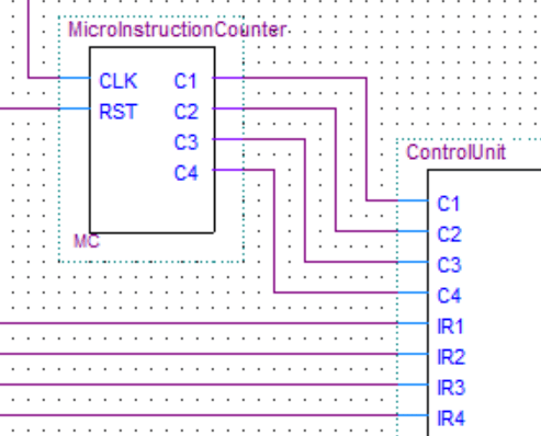
In the image below, you can see the ripple carry counter in the microinstruction counter.
A counter can also be made from other types of flip-flops. Here is an interactive example of a counter made from JK flip-flops.
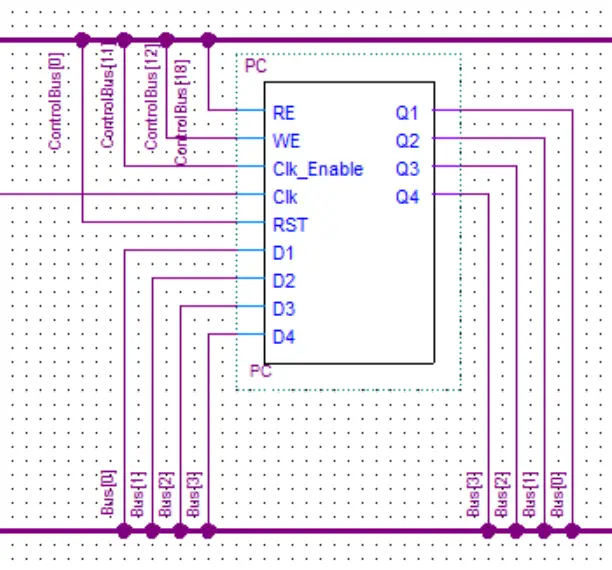
Program Counter
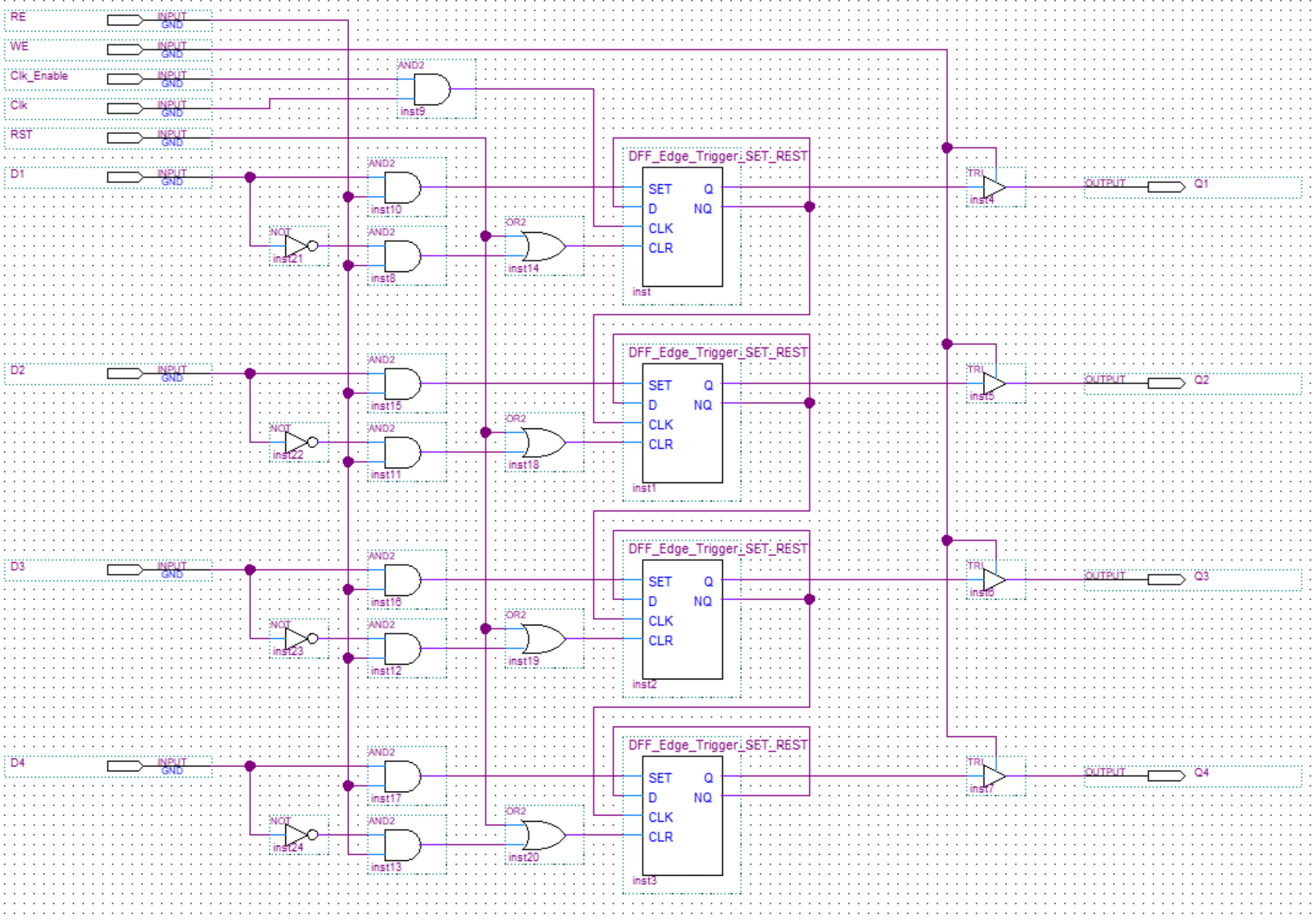
As already mentioned the program counter has tristate gates controlling its outputs and the ability to read in a value.
This is how the read enable circuits works: if read enable is high one of two things can happen:
If the input bit(D1 for example) is a 1 the first AND gate will output a 1 and activate the SET input on the flip-flop setting its stored value to 1.
If the input bit is 0 the second AND gate will output a 1 and activate the CLR input on the flip-flop setting its stored value to 0.