In this post, we’ll take a look at the clock module of my 8-bit computer. Ben used a 555 timer in his clock module to generate the clock signal for his breadboard computer. The approach I took is a bit different.
The DE0 Nano FPGA development board has an onboard 50 MHz crystal oscillator connected to one of the pins of the FPGA. This is where we can get our clock signal from. The problem is that the frequency is way too high for the computer and needs to be lowered. This can be accomplished by dividing the frequency using a frequency divider(which is esentially just a ripple-carry counter) or by using a PLL(phase locked loop).
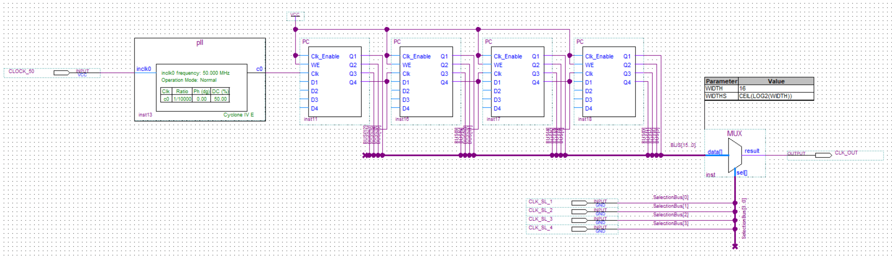
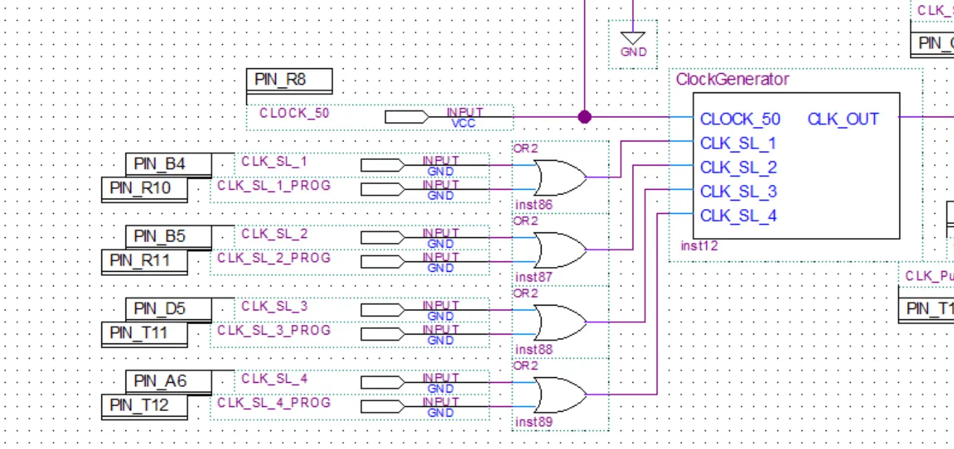
First I used a PLL to lower the frequnecy. Then I used multiple dividers with varying numbers of od division stages to get different frequencies. Finally a multiplexer was used to enable the selection of the desired frequency.
Frequency divider
First the 50 MHz input from the crystall oscilator is lowerd using a PLL. I won’t go into details about PLLs here(I’ll make a separate post just about them some time in the future).
Then the signal is feed into the PCs for further division. The program counter is in essence just a ripple-carry counter so I ended up reusing it as a frequency divider.