Measuring Capacitors And Inductors With Your Oscilloscope

Measuring Capacitors And Inductors With Your Oscilloscope Connections 2
Share:

About

In this post, I’ll show you how to measure the value of capacitors and inductors with your oscilloscope and waveform generator.

To measure the capacitor we’ll simply which will charge(periodically with a square wave) it through a resistor and measure how much time it takes the capacitor to charge to 63% we can then calculate its value according to the RC time constant formula which is t = RC. We’ll rearrange it to C = t/R to get out the capacitance.

To measure the inductor we’ll need to make an LC tank circuit. The rising edge of the square wave signal will cause it to ring. Then we can measure the frequency of the ringing which we can input into the LC tank formula L = 1/sqrt((2*Pi*f))*C and calculate the inductance.

Schematic

This is what it looks like on a piece of the prototype board.

Capacitor Measurement

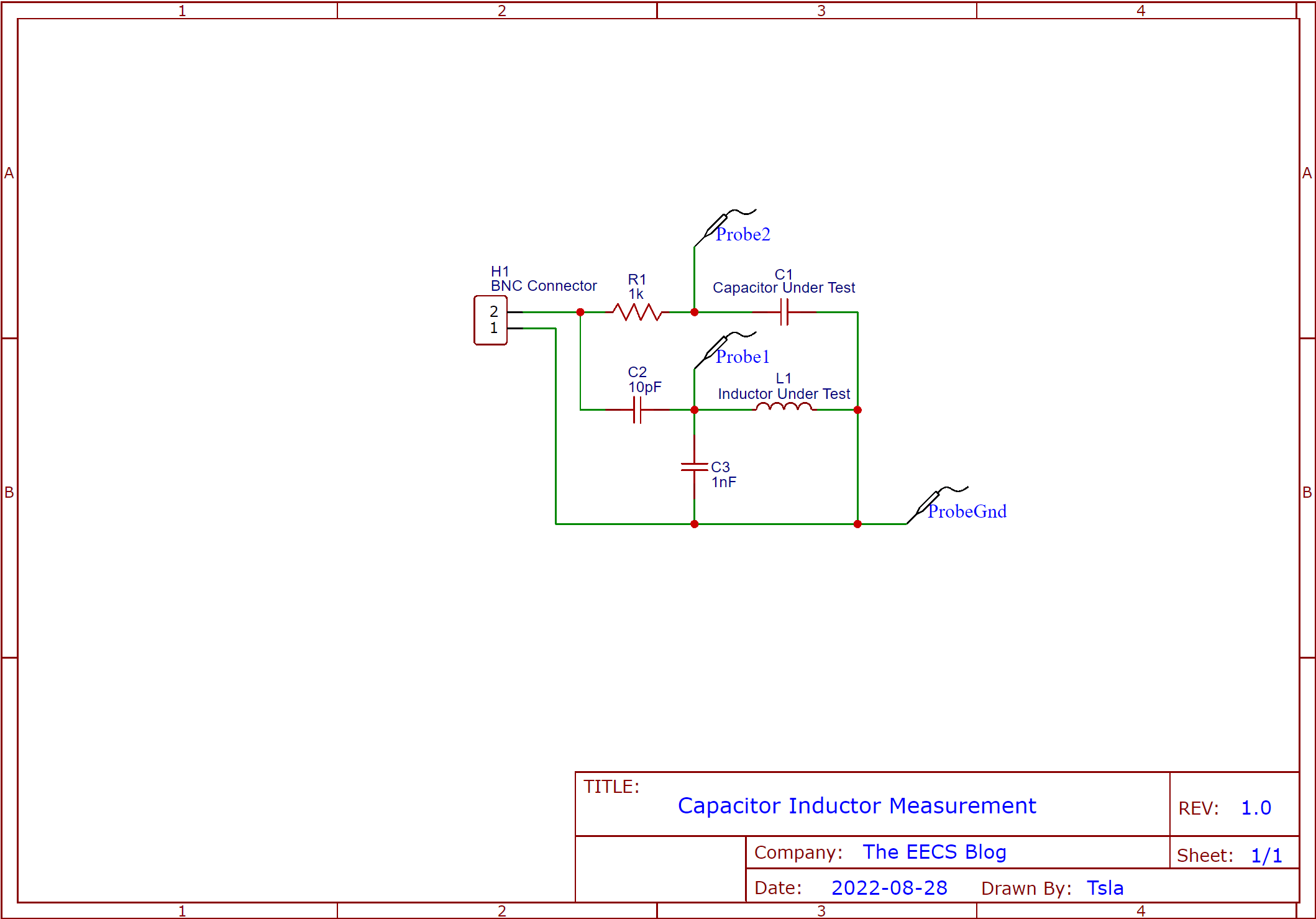
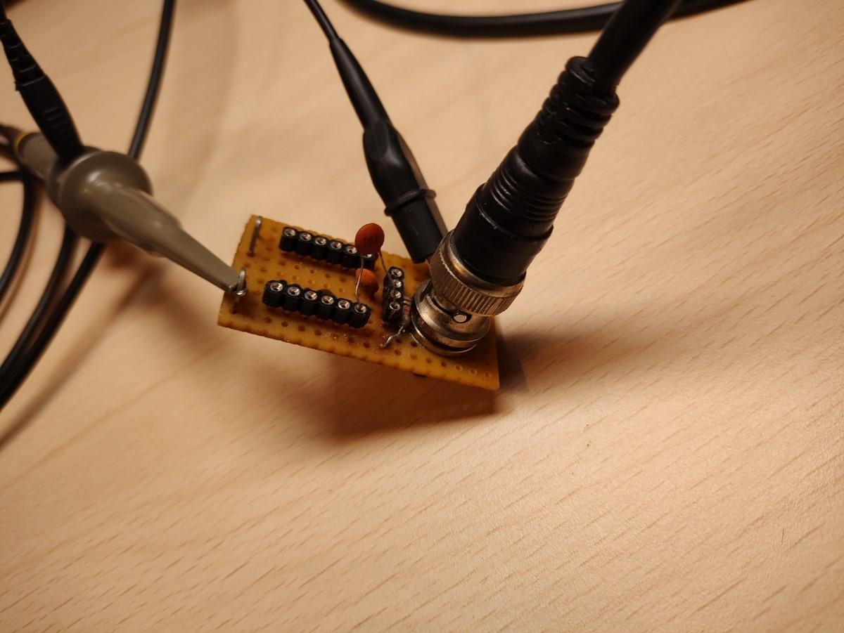
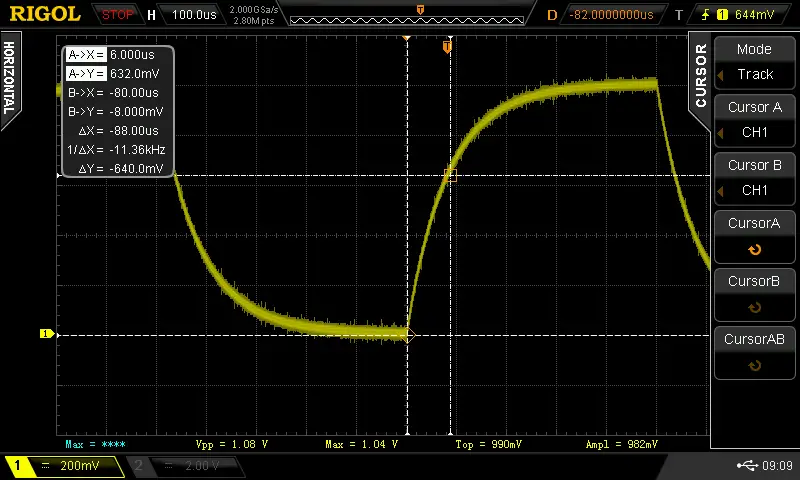
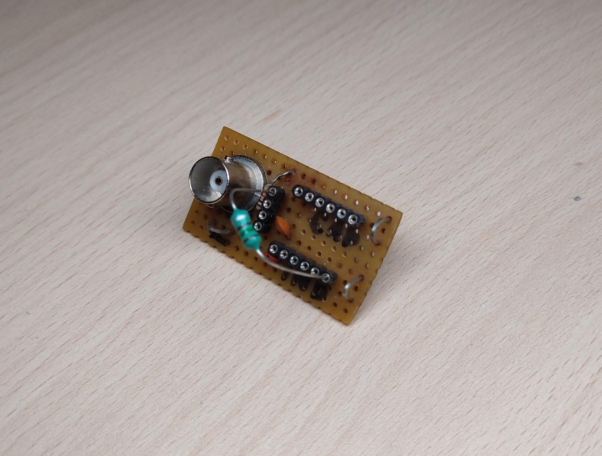
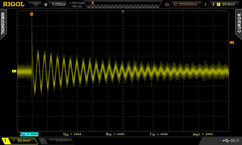
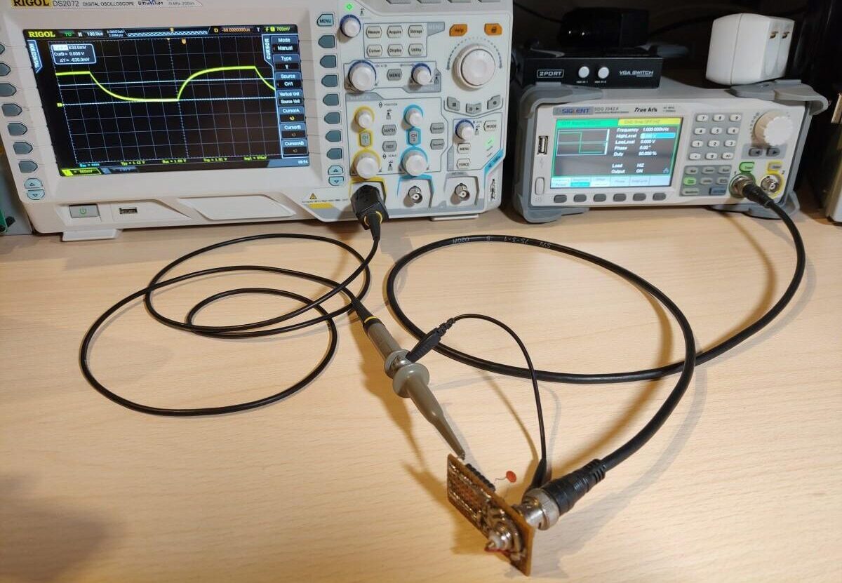
To measure the capacitor connect the oscilloscope probe to the capacitator measurement point and connect the BNC from the measurement circuit to the waveform generator. I set the generator to output a 1KHz square wave at 1V with a 50% duty cycle. Most of these parameters don’t matter that much. I set the voltage is 1Vpp because in this case the capacitor will be charged to 63% when the voltage reaches 630mV.
I turned on the cursors on the oscilloscope and set one marker at the beginning of the charge cycle and the other at around 630mV. The time ends up being 88uS so if we put this into the equation C = 0.000088/1000 we get a C of 88nF or 0.088uF.
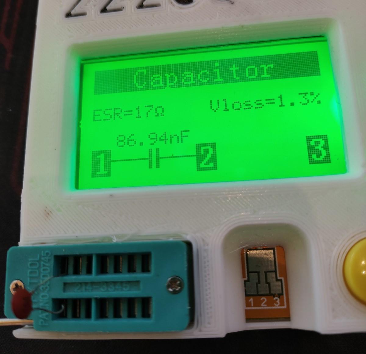
The capacitor has a code of 104 which means it’s supposed to have a capacitance of 0.1uF. The difference between our measured value and the rated value is due to the poor tolerance of the capacitor. I confirmed that by measuring the capacitor with a component tester which showed almost the exact same value that was measured.

Inductor measurement

To measure the inductor connect the setup in the same way except the oscilloscope probe needs to be hooked up to the inductor measurement point.
I turned on the cursors on the oscilloscope and measured the peek to peek time to determine the frequency of the ringing which came out to be 463Khz.
If we put this into the equation L = 1/sqrt((2*Pi*463KHz))*1nF we get an L of 118.16uH or around 0.12mH. I used the component tester to verify the result and it comes pretty close.
Share:

Leave a Reply

Your email address will not be published. Required fields are marked *

The following GDPR rules must be read and accepted:
This form collects your name, email and content so that we can keep track of the comments placed on the website. For more info check our privacy policy where you will get more info on where, how and why we store your data.

Advertisment ad adsense adlogger