About
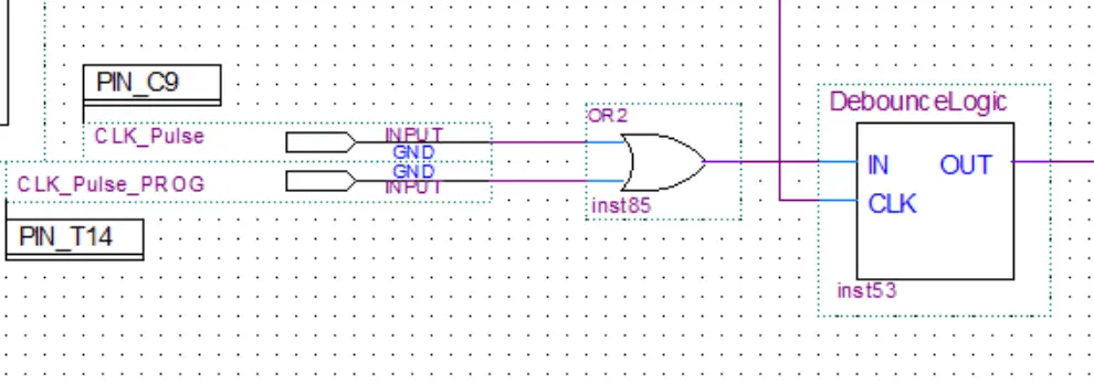
In this post, we’ll take a look at the button debounce module of my 8-bit computer. Ben used a 555 timer in his clock module to make a delay to debounce the button. I took a different approach.
I took the 50 MHz input from the crystal oscillator and lowered the frequency by using another clock module. This way I have another slower clock signal independent from the main clock. This slow frequency is then fed into the debounce modules.
Button Bounce Problem
When a button gets pressed the two metallic contacts inside it will touch together completing the circuit. It often happens that some bounces/vibrations will occur when the contacts first touch resulting in a few voltage spikes.
This is problematic as it’s interpreted as multiple button presses when in reality the button was only pressed once.
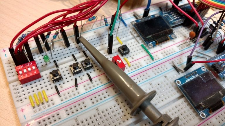
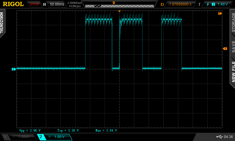
To show the problem I used an oscilloscope to probe a button output before it goes through the debounce circuit.
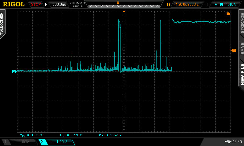
Three presses of the button were made(see the first image). Everything seems fine but if we zoom in on the second button press you can see contact bounce occurring(see the second image). To fix this issue we have to debounce the button.
Button Debounce Circuit
There are a lot of ways to debounce a button. I used two D flip-flops feed by a slow clock signal from a secondary clock module(set up specifically to provide a slower clock signal just for the debounce modules).
The first flip-flop stores the current button value meanwhile the second flip-flop stores the previous value. If both values are 1 this means the button was being pressed for the length of the clock cycle and it wasn’t just a voltage spike from the contact bounce. Therefore a 1 will be output.

