Home


About
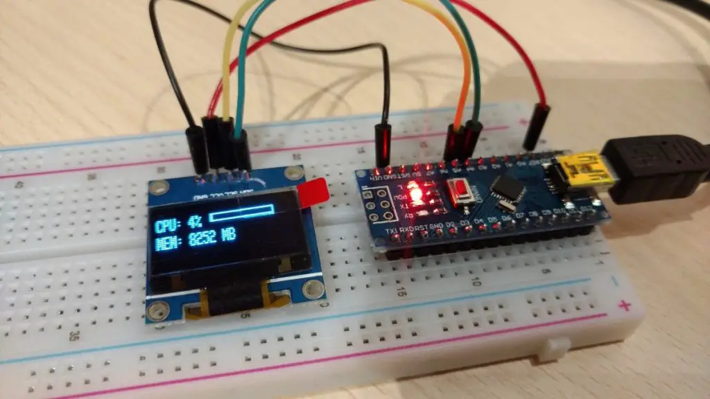
In this post, we will learn how to send/receive multiple values at once to/from the Arduino over the serial port. In this specific case, I want to display my computer’s CPU and RAM usage on an ssd1306 display. To do that I have to send more than one value at once over the serial port to the Arduino.
Hardware Used
- #adAmazon LinkArduino Nano
- #adAmazon LinkSSD1306 OLED Screen
- #adAmazon LinkBreadboard
Sending Multiple Values
To send multiple values we will simply send a string with our values separated by a special character of our choice. In this case, I will use a comma to separate the values. I will show you how to do that later on.
Receiving Values
Getting the values is a little bit more complicated. If this was just a C# Windows app running on a regular PC getting the values from the string would be pretty easy. We would just use the Split() function to split the string into an array when the specified character is encountered. Then our values would be stored in that array in the order that they were in the string
Example:
receivedString = "15,25,";
string[] values = receivedString.Split(',');
string value1 = values[0];
string value2 = values[1]; But with the Arduino, we have to put in a bit more work and do this manually.
Complete Arduino Code Example
This Arduino sketch displays the CPU and RAM usage of my PC so there is some extra code here. There is an app on the PC that tracks CPU and RAM usage and sends the data over the serial port to the Arduino to be displayed. If you are interested in this little project of mine you can check it out here. I also made this tutorial that explains all about how to connect to and control the Arduino from a Windows App on your PC.
For the explanation of the code read the comments.
//Include library
#include  <Adafruit_GFX.h>
#include  <Adafruit_SSD1306.h>

#define OLED_RESET 4
Adafruit_SSD1306 display(OLED_RESET);

//Variables.
int cpuValue = 0;
String cpuValueString = "0";
String memValueString = "0";
String strArr[2]; //Set the size of the array to equal the number of values you will be receiveing.

void setup()
{
    //Initialize display by providing the diplay type and its I2C address.
    display.begin(SSD1306_SWITCHCAPVCC, 0x3C);

    //Start serial.
    Serial.begin(9600);
    Serial.println("Ready to display.");

    //Display setup.
    display.clearDisplay();
    display.setTextSize(1);
    display.setTextColor(WHITE);
}

void loop()
{
    String rxString = "";

    if (Serial.available()) {
        cpuValueString = "";

        //Keep looping until there is something in the buffer.
        while (Serial.available()) {
            //Delay to allow byte to arrive in input buffer.
            delay(2);
            //Read a single character from the buffer.
            char ch = Serial.read();
            //Append that single character to a string.
            rxString += ch;
        }

        int stringStart = 0;
        int arrayIndex = 0;

        for (int i = 0; i  < rxString.length(); i++) {
            //Get character and check if it's our "special" character.
            if (rxString.charAt(i) == ',') {
                //Clear previous values from array.
                strArr[arrayIndex] = "";

                //Save substring into array.
                strArr[arrayIndex] = rxString.substring(stringStart, i);
                //Set new string starting point.
                stringStart = (i + 1);
                arrayIndex++;
            }
        }

        //Put values from the array into the variables.
        cpuValueString = strArr[0];
        memValueString = strArr[1];

        //Convert string to int.
        cpuValue = cpuValueString.toInt();
    }

    //Clear display.
    display.clearDisplay();

    //CPU Text value display.
    display.setCursor(0, 5);
    display.print("CPU: " + cpuValueString + "%");

    //MEM Text value display.
    display.setCursor(0, 15);
    display.print("MEM: " + memValueString + " MB");

    //Progress bar display.
    //x,y,w,h
    display.drawRect(50, 5, 60, 5, WHITE);
    display.fillRect(50, 5, (cpuValue * 0.6), 5, WHITE);

    //Update display.
    display.display();
    delay(1);
}
Just The Relevant Code
Above I included the whole code so it’s easier to see how it all fits together. Here is just the part where we get the values from the serial port.
if(Serial.available()){
String rxString = "";
String strArr[2]; //Set the size of the array to equal the number of values you will be receiveing.
//Keep looping until there is something in the buffer.
while (Serial.available()) {
//Delay to allow byte to arrive in input buffer.
delay(2);
//Read a single character from the buffer.
char ch = Serial.read();
//Append that single character to a string.
rxString+= ch;
}
int stringStart = 0;
int arrayIndex = 0;
for (int i=0; i < rxString.length(); i++){
//Get character and check if it's our "special" character.
if(rxString.charAt(i) == ','){
//Clear previous values from array.
strArr[arrayIndex] = "";
//Save substring into array.
strArr[arrayIndex] = rxString.substring(stringStart, i);
//Set new string starting point.
stringStart = (i+1);
arrayIndex++;
}
}
//Put values from the array into the variables.
String value1 = strArr[0];
String value2 = strArr[1];
//Convert string to int if you need it.
int intValue1 = value1.toInt();
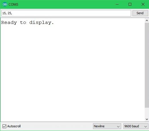
} Send Values Using Serial Monitor
For a simple demonstration I will send the values to the Arduino using the serial monitor included in the Arduino IDE. The values will be sent separated by a comma like so 15,25,.
Sending Values From An App
In my case, I will be sending CPU and RAM usage data from a Windows app. If you would like to know how to do that see this post. Here is just a code snippet to help you visualize how it works. As you can see we first take the values and convert them to a string. Then the values get concatenated with commas in between them. Finally, the whole string gets written to the serial port.
Code in application running on the PC:

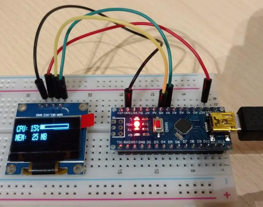
Arduino showing the data:
About
In this tutorial, you will learn how to install Windows 10 IOT on the Raspberry Pi 3.
Hardware Used
- #adAmazon LinkRaspberry Pi
About Winndows 10 IOT
I won’t really go in too much detail about Windows 10 IOT. You can read about all the boring details here. Long story short it is a version of Windows meant for IOT(internet of things) purposes. It can run UWP apps(see how to do that here) and can be used with the following supported chips. Most notably it can be run on a Raspberry Pi.
Installing Windows 10 IOT on a Raspberry Pi
First, get the IOT Dashboard here: https://docs.microsoft.com/en-us/windows/iot-core/connect-your-device/iotdashboard, download, install and open it.

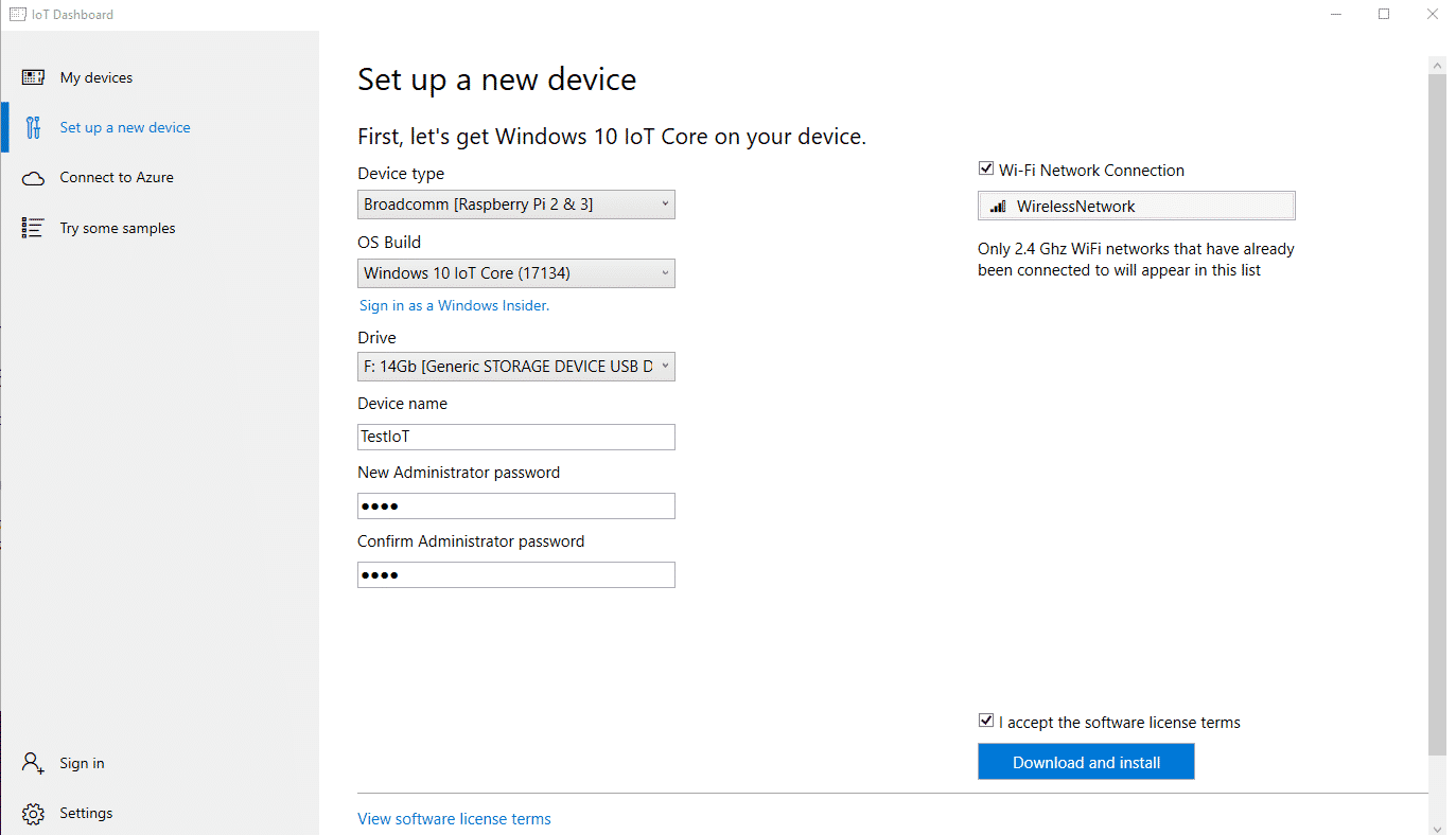
Click on Set up a new device and then:
-
- Select Raspberry Pi as your board.
- Select Windows IOT Core as the OS.
- Plug in the sd card and select it.
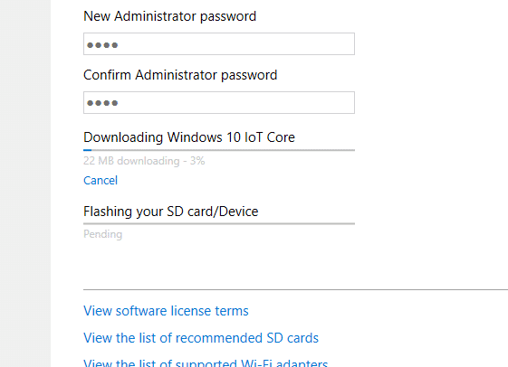
- Name the device and set a password.
- Finally, click Download and install and wait for the installation to complete.
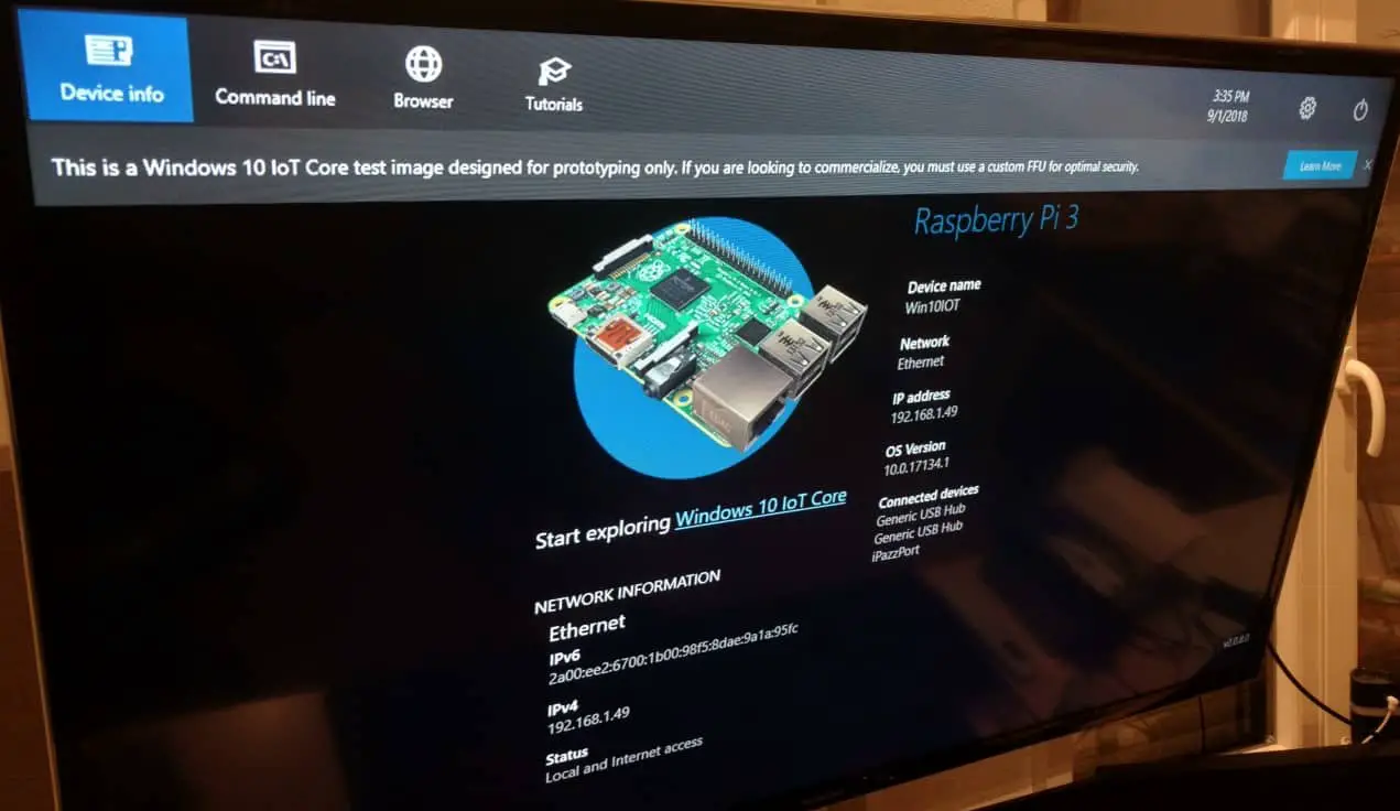
All done.
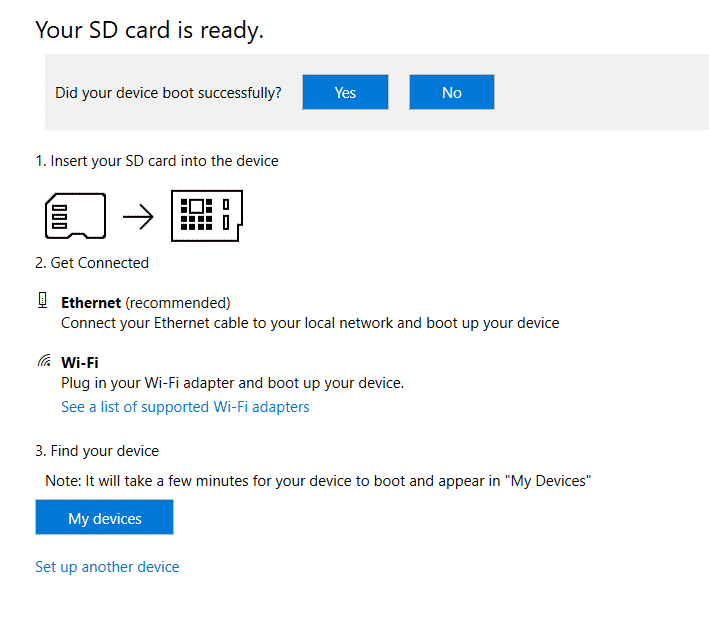
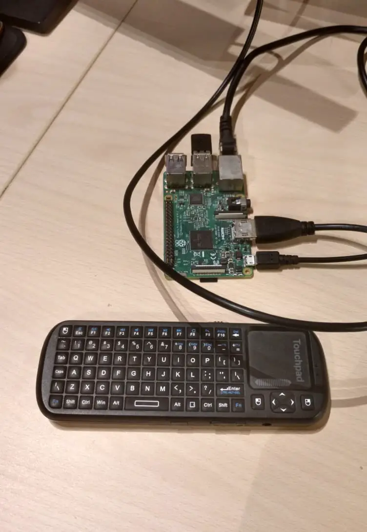
Insert the SD card into your Raspberry Pi and connect power to it. Windows IOT will begin to boot up automatically.
Upon the first boot up, you will have to set up a few basic settings like the internet connection, Cortana settings, language, etc, … It’s all pretty intuitive and straight forward stuff so I just left it out of the tutorial.
And you are all done! If you are interested in making an app and deploying it to the Raspberry Pi running Windows 10 IOT check out this post.
About
In this tutorial, we will be using Visual Studio to make a C# Windows Forms Application. The app will communicate with the Arduino over a serial port. The Arduino will be programmed to turn on or off an LED based on what it receives from the App.
Hardware Used
- #adAmazon LinkArduino
Windows App
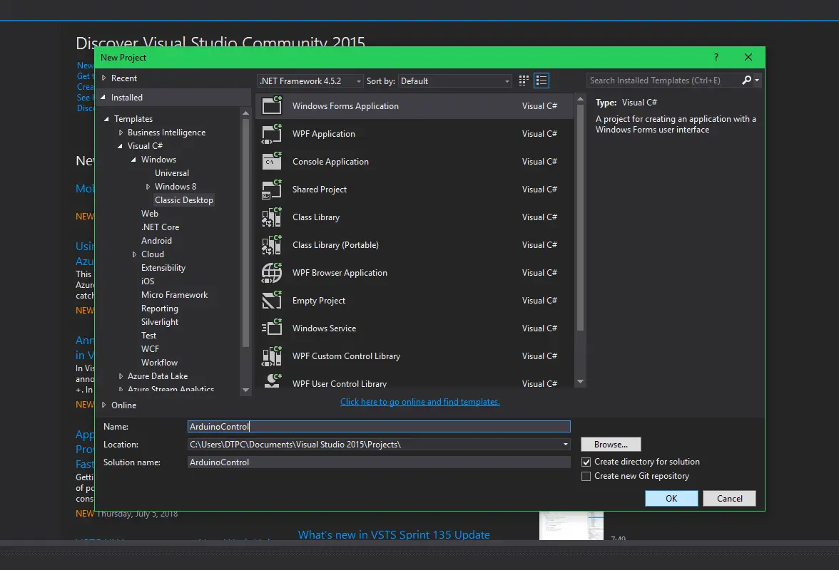
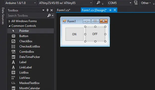
Open up visual studio and create a new wfa(windows frorms application) project.
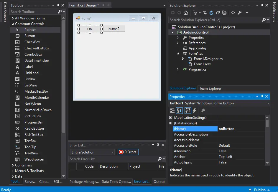
Add two buttons, set the text of one to ON and the other to OFF.
Add two buttons, set the text of one to ON and the other to OFF. In the properties window find the name property and rename the on button to onButton. Do the same thing for the off button(writing off instead of on of course).
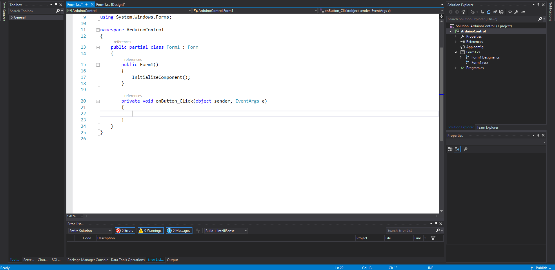
Next, double click on the on button to make an event handler for it. Do the same for the off button. Whenever the button gets clicked the code inside the event handler will get executed.
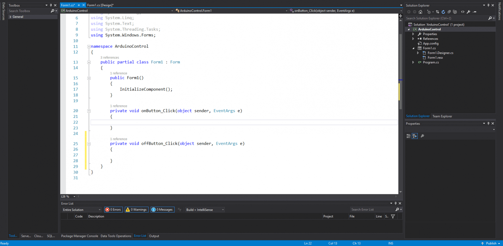
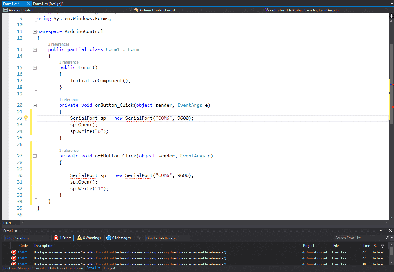
Insert this code into the event handlers(for the off button change the Write() parameter from “1” to “0”):
//Setup port by providing the port name and baud rate.
SerialPort sp = new SerialPort("COM6", 9600);
//Open port.
sp.Open();
//Write to port.
sp.Write("1");
//Close port.
sp.Close();
As of right now just replace the “COM6” with the name of whatever port your Arduino is currently connected to. Later on, we’ll implement a dropdown to choose a port from.
There will be an error saying that SerialPort couldn’t be found. To fix it include the serial port namespace. Just press Ctrl + . and select using System.IO.Ports. This using System.IO.Ports; line will be added to the top of your file and all the errors should be gone.

This should all work but it’s a really good idea to implement exception handling when dealing with serial ports. For example, if the port isn’t available or doesn’t exist our application will throw an exception. If left unhandled the exception will crash the app, to prevent this we need to handle the exception and give the user a message saying we couldn’t connect to the port.
Here’s the full code:
using System;
using System.Collections.Generic;
using System.ComponentModel;
using System.Data;
using System.Drawing;
using System.IO.Ports;
using System.Linq;
using System.Text;
using System.Threading.Tasks;
using System.Windows.Forms;

namespace ArduinoControl
{
    public partial class Form1 : Form
    {
        public Form1()
        {
            InitializeComponent();
        }

        private void onButton_Click(object sender, EventArgs e)
        {
            try
            {
                SerialPort sp = new SerialPort("COM6", 9600);
                sp.Open();
                sp.Write("1");
                sp.Close();
            }
            catch (Exception ex)
            {
                MessageBox.Show(ex.Message);
            }

        }

        private void offButton_Click(object sender, EventArgs e)
        {
            try
            {
                SerialPort sp = new SerialPort("COM6", 9600);
                sp.Open();
                sp.Write("0");
                sp.Close();
            }
            catch (Exception ex)
            {
                MessageBox.Show(ex.Message);
            }
        }
    }
}
The Arduino Part
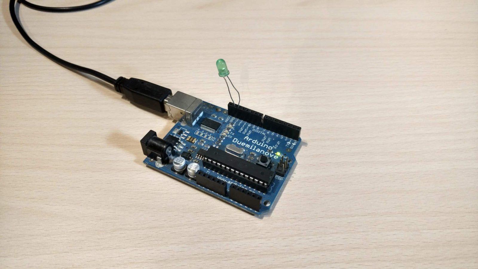
Hardware
Connect the LED from PIN 13 to GND.
Software
The Arduino code is very simple. First, we declare pin 13 as an output and begin serial communication at a baud rate of 9600. In the loop, we read the serial data and check whether a 1 or a 0 was received. If one is received the output gets turned on else it gets turned off.
int ledPin = 13;
void setup()
{
pinMode(ledPin, OUTPUT);
Serial.begin(9600);
}
void loop()
{
char ch;
while(Serial.available() > 0)
{
ch = Serial.read();
if (ch == '1')
{
digitalWrite(ledPin, HIGH);
}
else if (ch == '0')
{
digitalWrite(ledPin, LOW);
}
}
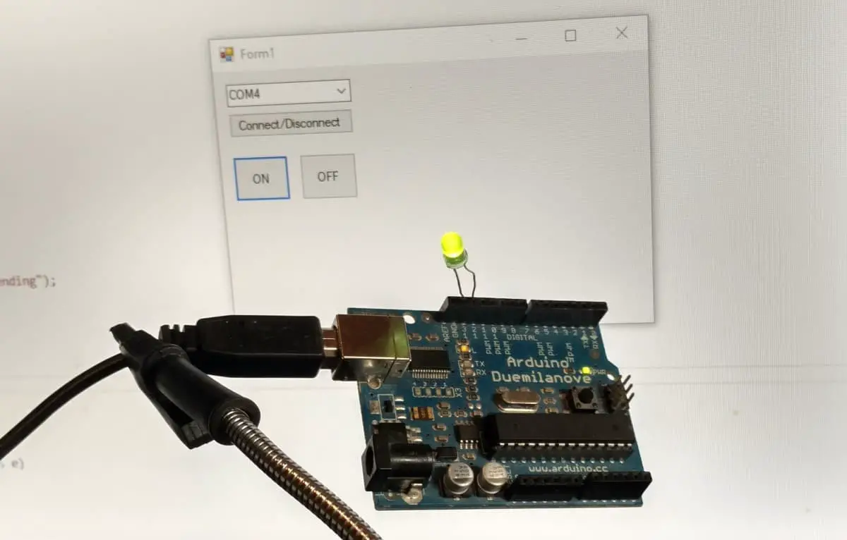
} Result
Improvements
Right now the COM port is hardcoded so it has to be changed in the code every time. I did this for demonstration purposes as it’s the simplest way(and not the best way) to make a connection. Instead, we should be able to get all the available ports in a dropdown menu and select the one we want to connect to.
Update the GUI by adding a connect/disconnect button and adding a dropdown menu/combo box.
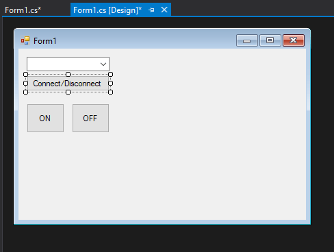
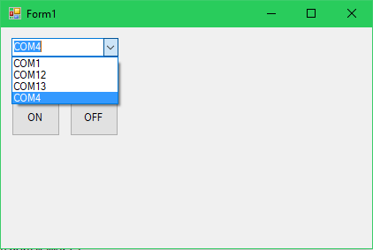
And update the code like so.
using System;
using System.Collections.Generic;
using System.ComponentModel;
using System.Data;
using System.Drawing;
using System.IO.Ports;
using System.Linq;
using System.Text;
using System.Threading.Tasks;
using System.Windows.Forms;

namespace ArduinoControl
{
    public partial class Form1 : Form
    {
        bool connected = false;
        SerialPort sp;
        public Form1()
        {
            InitializeComponent();
            var ports = SerialPort.GetPortNames();
            portComboBox.DataSource = ports;
        }

        private void onButton_Click(object sender, EventArgs e)
        {
            try
            {
                if (connected)
                {
                    sp.Write("1");
                }
                else
                {
                    MessageBox.Show("Connect to a port before sending");
                }
            }
            catch (Exception ex)
            {
                MessageBox.Show(ex.Message);
            }

        }

        private void offButton_Click(object sender, EventArgs e)
        {
            try
            {
                if (connected)
                {
                    sp.Write("0");
                }
                else
                {
                    MessageBox.Show("Connect to a port before sending");
                }

            }
            catch (Exception ex)
            {
                MessageBox.Show(ex.Message);
            }
        }

        private void connectButton_Click(object sender, EventArgs e)
        {
            try
            {

                sp = new SerialPort(portComboBox.SelectedItem.ToString(), 9600);

                if (!connected)
                {
                    sp.Open();
                    connected = true;

                    MessageBox.Show("Serial port connected.");
                }
                else
                {
                    sp.Close();
                    sp.Dispose();

                    connected = false;

                    MessageBox.Show("Serial port disconnected.");
                }

            }
            catch (Exception ex)
            {
                MessageBox.Show(ex.Message);
            }
        }
    }
}

About
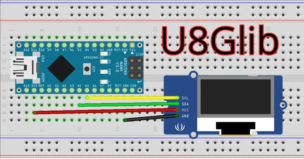
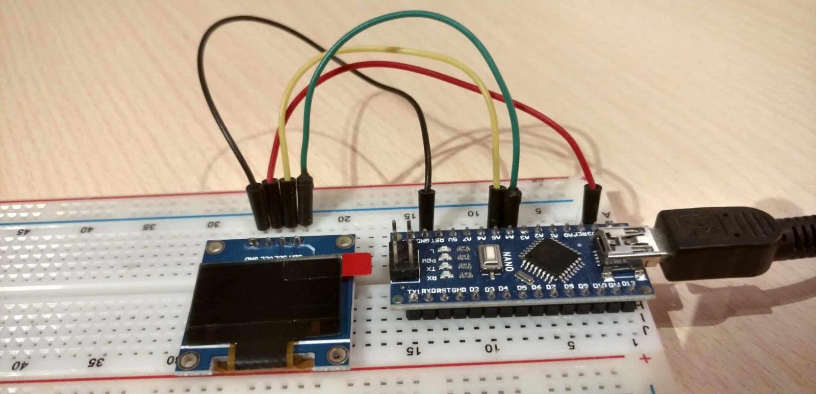
This tutorial covers how to connect an SSD1306 0.96 inch OLED screen to an Arduino Nano over I2C and display text on it using the U8Glib library.
Hardware Used
- #adAmazon LinkArduino Nano
- #adAmazon LinkSSD1306 OLED Screen
- #adAmazon LinkBreadboard
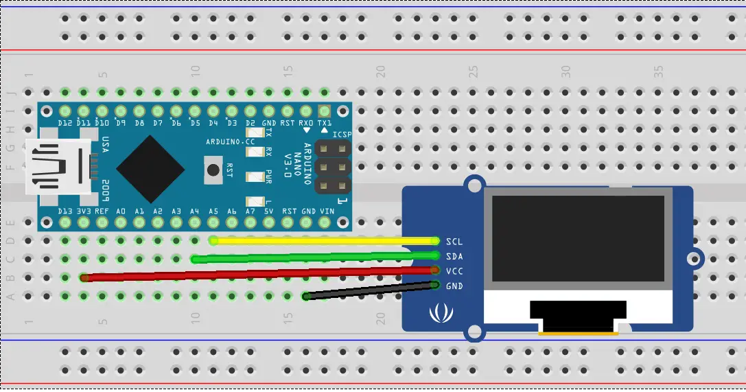
Hardware Connections
| Arduino | OLED |
|---|---|
| 3.3V | Vdd |
| Gnd | Gnd |
| Analog 4 | SDA |
| Analog 5 | SCK |
U8Glib Install
In this tutorial, I will be using the U8Glib graphics library for the screen. In this tutorial, I do the same but using Adafruits SSD1306 graphics library.
Method 1:
Downaload the library: https://github.com/olikraus/U8glib_Arduino/releases/tag/1.19.1
In the Arduino IDE :
sketch > include library > Add .ZIP Library > select the downloaded ZIP
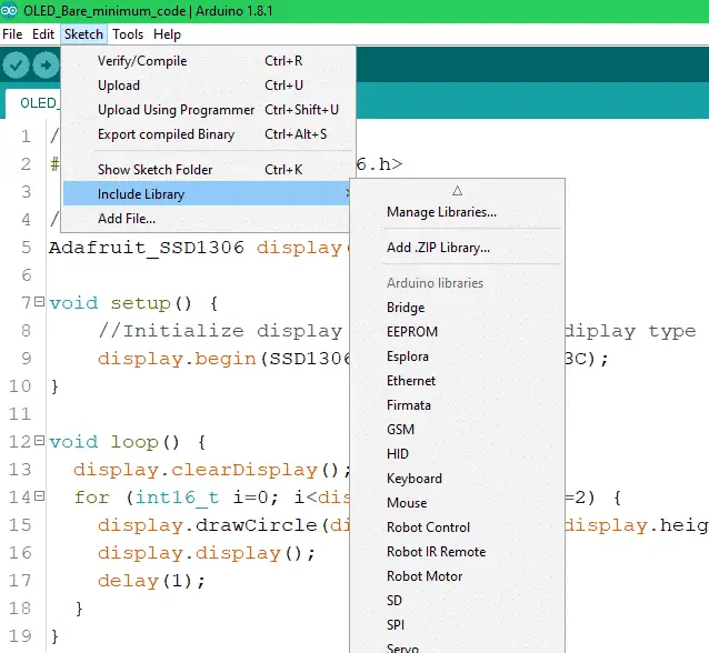
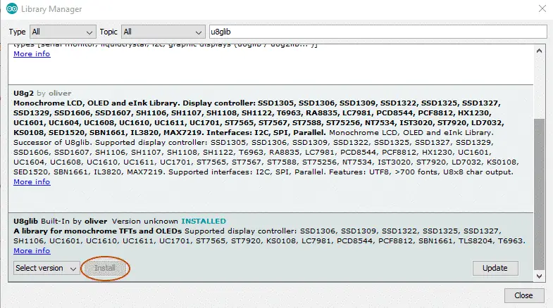
Method 2:
Or go to sketch > include library > manage libraries > type u8glib in the search bar and click on install.
Code
Here is the bare minimum code to make the display work. If you need more info about the library check out the documentation on GitHub. You can find more examples provided in the Arduino IDE: File > Examples > U8glib.
//Include the graphics library.
#include "U8glib.h"

//Initialize display.
U8GLIB_SSD1306_128X64 u8g(U8G_I2C_OPT_NONE | U8G_I2C_OPT_DEV_0);

void setup(void)
{
    //Set font.
    u8g.setFont(u8g_font_unifont);
}

void loop(void)
{

    u8g.firstPage();
    do {
        draw();
    } while (u8g.nextPage());

    //Delay before repeating the loop.
    delay(50);
}

void draw(void)
{

    //Write text. (x, y, text)
    u8g.drawStr(20, 40, "Hello World.");
}
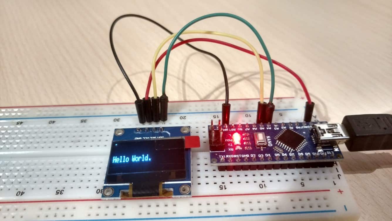
Hello World!
Upload the above-provided code and you should have a Hello World.

About
This tutorial covers how to connect an SSD1306 0.96 inch OLED screen to an Arduino Nano over I2C and display text on it.
Hardware Used
- #adAmazon LinkArduino Nano
- #adAmazon LinkSSD1306 OLED Screen
- #adAmazon LinkBreadboard
Hardware Connections
| Arduino | OLED |
|---|---|
| 3.3V | Vdd |
| Gnd | Gnd |
| Analog 4 | SDA |
| Analog 5 | SCL |
Software Libraries
In this tutorial, I will be using Adafruits graphics library for the screen. In this tutorial, I do the same but using the U8Glib graphics library.
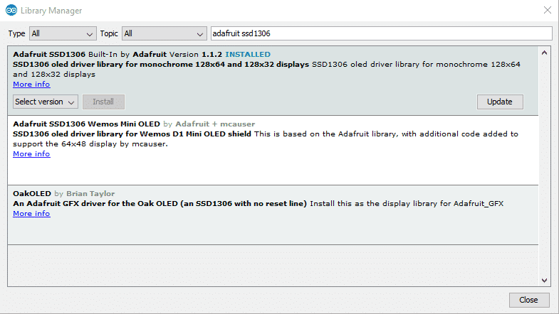
First, we need to install the Adafruit graphics library like so:
Sketch > Include Library > Manage Libraries
Search for and install the Adafruit SSD1306 library.
Find the I2C address of the OLED screen
Upload this code:
Source: https://playground.arduino.cc/Main/I2cScanner/
This is an I2C address scanner. It will tell you the addresses of all connected devices. What this code essentially does is it goes through all the addresses and sends a message to each one. If it gets a response from it the address will be sent over the serial port.
// --------------------------------------
// i2c_scanner
//
// Version 1
// This program (or code that looks like it)
// can be found in many places.
// For example on the Arduino.cc forum.
// The original author is not know.
// Version 2, Juni 2012, Using Arduino 1.0.1
// Adapted to be as simple as possible by Arduino.cc user Krodal
// Version 3, Feb 26 2013
// V3 by louarnold
// Version 4, March 3, 2013, Using Arduino 1.0.3
// by Arduino.cc user Krodal.
// Changes by louarnold removed.
// Scanning addresses changed from 0...127 to 1...119,
// according to the i2c scanner by Nick Gammon
// http://www.gammon.com.au/forum/?id=10896
// Version 5, March 28, 2013
// As version 4, but address scans now to 127.
// A sensor seems to use address 120.
// Version 6, November 27, 2015.
// Added waiting for the Leonardo serial communication.
//
//
// This sketch tests the standard 7-bit addresses
// Devices with higher bit address might not be seen properly.
//

#include <Wire.h>

void setup()
{
    Wire.begin();

    Serial.begin(9600);
    while (!Serial); // Leonardo: wait for serial monitor
    Serial.println("\nI2C Scanner");
}

void loop()
{
    byte error, address;
    int nDevices;

    Serial.println("Scanning...");

    nDevices = 0;
    for (address = 1; address < 127; address++) {
        // The i2c_scanner uses the return value of
        // the Write.endTransmisstion to see if
        // a device did acknowledge to the address.
        Wire.beginTransmission(address);
        error = Wire.endTransmission();

        if (error == 0) {
            Serial.print("I2C device found at address 0x");
            if (address < 16)
                Serial.print("0");
            Serial.print(address, HEX);
            Serial.println(" !");

            nDevices++;
        }
        else if (error == 4) {
            Serial.print("Unknown error at address 0x");
            if (address < 16)
                Serial.print("0");
            Serial.println(address, HEX);
        }
    }
    if (nDevices == 0)
        Serial.println("No I2C devices found\n");
    else
        Serial.println("done\n");

    delay(5000); // wait 5 seconds for next scan
}
Open the serial monitor(ctrl+shift+m), select the COM port of your device and select the baud rate that was specified in the code(9600).
You should now be seeing the I2C addresses of all present devices.
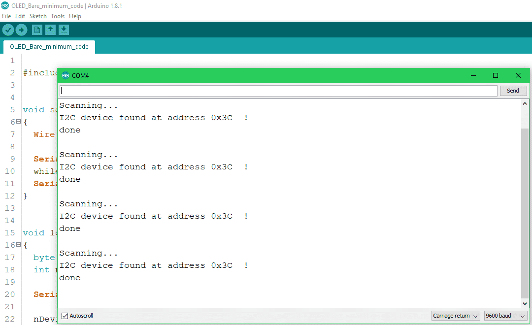
Now take the address and put it in as an input parameter of the display initialization function like so: display.begin(SSD1306_SWITCHCAPVCC, 0x3C);
Code
Here is the bare minimum code to make the display work and write out some text. If you need more examples for such things as drawing shapes check out the examples provided in the Arduino IDE. You can find them under: File > Examples > Adafruit SSD1306.
//Include library
#include <Adafruit_GFX.h>
#include <Adafruit_SSD1306.h>

#define OLED_RESET 4
Adafruit_SSD1306 display(OLED_RESET);

void setup()
{
    //Initialize display by providing the display type and its I2C address.
    display.begin(SSD1306_SWITCHCAPVCC, 0x3C);

    //Set the text size and color.
    display.setTextSize(1);
    display.setTextColor(WHITE);
}

void loop()
{
    //Clear previous image.
    display.clearDisplay();

    display.setCursor(0, 15);
    display.print("Hello World.");

    //Display changes if any were made.
    display.display();
    delay(1);
}
Hello World!
Upload the above-provided code and you should have a Hello World.

About
Some time ago I bought a USB flash drive online from China. When I plugged it into my PC Windows Defender detected that malware(seems like a crypto miner) was present on the flash drive.
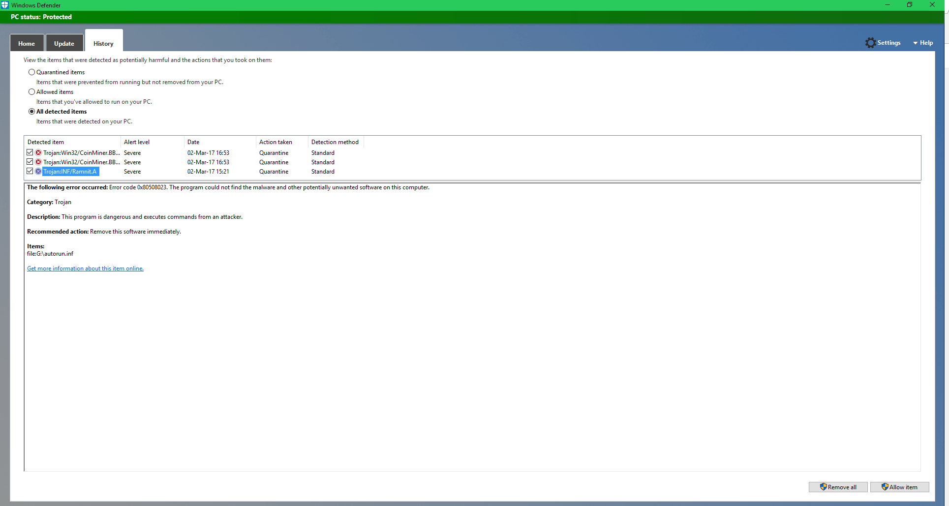
In the image below you can see the contents. It seems like autorun.inf was supposed to run when the USB gets plugged in. However, this feature was disabled in Windows many years ago to protect users from this exact type of attack. So the malware either targets older systems or the attackers simply hope that the user clicks the file.
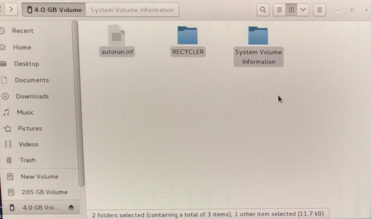
So I guess you should be careful with any storage device you buy and always format it before using it. The malware shouldn’t be able to come back after that unless the attackers have put some serious effort into modding the USB drives hardware or its memory controllers’ firmware. I would assume that only certain government agencies are capable and willing to do that if they are going after a specific target/goal. So the average user (probably) doesn’t have to worry about it.
As far as who and when they put the malware on the USB is hard to say. It could have happened at almost any point in the supply chain: employee at the factory where the USB is manufactured, the seller(or one of their employees), or any other middle man that buys and resells the drives within Cina before they get to the final seller that sells them online.
Also this isn’t an isolated incident as according to the FBI a similar thing has happened to a company that bought thumb drives that originated from China.
About
Some time ago I bought a NAZE32 F3 flight controller for less than 10$ thinking I could use it for a cheap quadcopter build. But when I tried configuring the GPS it didn’t work. At first, I thought I did something wrong or there was a bug, but as it turns out the GPS feature was removed for F3 flight controllers. The frustrating thing is that this isn’t mentioned anywhere. As a result, I spent hours trying to figure out what the problem was until I found out that the feature was removed. Anyway, the solution is to manualy add in the GPS feature yourself and compile your own version of the firmware.
What we will be doing
In this post, we’ll take a look at how to add/remove features from Cleanflight/Beatflight. In this instance, I will be adding the GPS feature back and remove some of the other features to free up enough resources for the GPS. Using the same process you can add/remove any features you want.
Prerequsites
Before we get started I will assume that you already have the development environment set up and know how to compile the firmware. If you don’t you can check out this tutorial on how to compile the firmware and this tutorial on how to set up Ubuntu on Windows.
Hardware used
- #adAmazon LinkF3 Flight Controller
How to do it
If you followed my tutorial on compiling the firmware your Cleanfilght folder is in Ubuntu. If you want you can keep it there and edit the files using the command line with an editor like nano or vim.
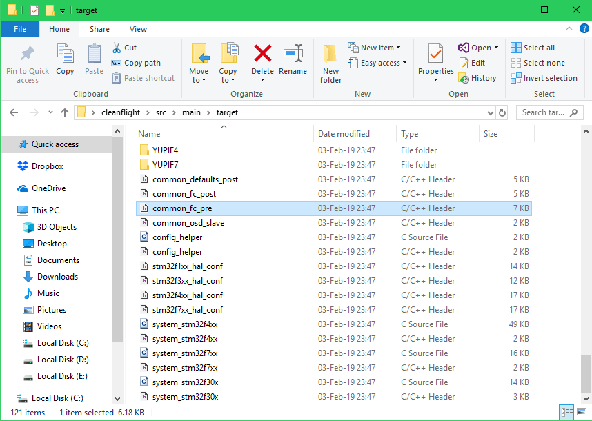
I will first move the Cleanflight folder from Linux to Windows so I can more easily edit the code. Also, you can just download the source code from Github and then unzip the files to your desktop.
Using the mv command to move the folder to the Windows desktop.
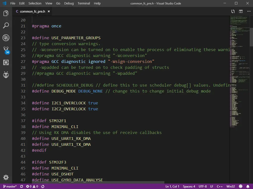
Now that the cleanflight folder is on the desktop, let’s navigate to src\main\target and open up the common_fc_pre.h file in a text editor.
In this file, we can define which features get used. In the following code, you can see that some features will only be available if your controller has more than a specified amount of memory. For example, the GPS feature that I am interested in is only available for the controllers with more than 256 KB of memory. But my F3 controller only has 128KB of memory. So I ‘ll have to move the #define USE_GPS line of code from this if statement #if (FLASH_SIZE > 256) to this if statement #if (FLASH_SIZE > 128).
Before:
After:
Now we have the problem of not having enough memory. To fix this we will just remove some unneeded features.
You can set all the features that you don’t use to #undef. I use the Frsky receiver so everything except USE_SERIALRX_SBUS can be set to #undef.
Code after removing unused features.
You can keep going through the code removing things that you don’t need(in my case that was not necessary.). If you don’t know what a particular line of code does google it. And if you still don’t know what it does then leave it alone. After you are done compile the firmware.
Open up the Ubuntu terminal, navigate to the Cleanflight folder and compile.
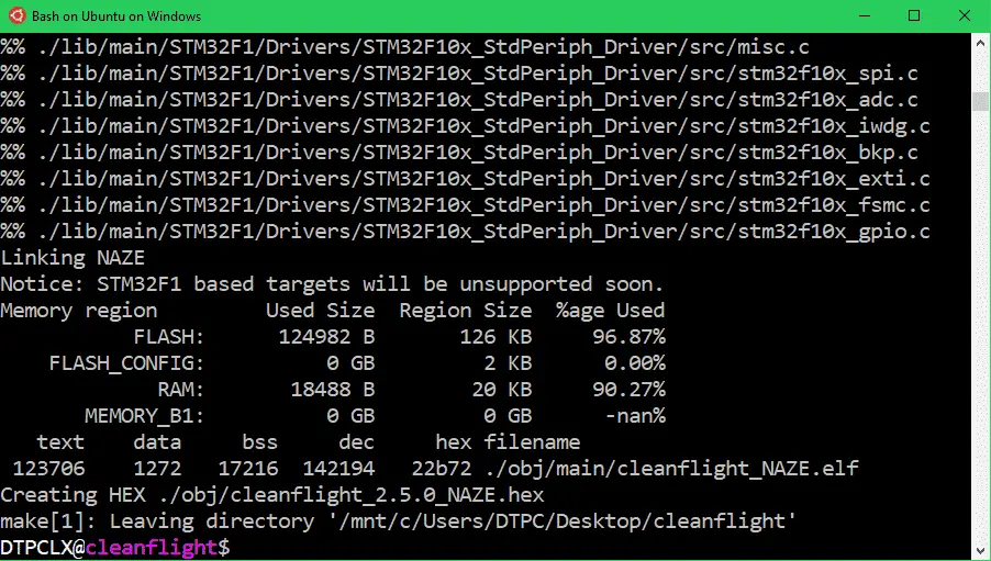
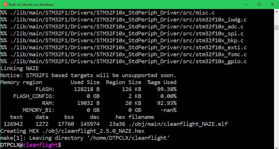
Firmware after adding/removing features.
Original firmware without modifications.
As you can see the modified firmware now uses fewer resources than the original one so we are all good(You must make sure that all the numbers are the same or lower than in the original firmware).
And this is it. You can find your .hex file in Cleanflight\obj. All that’s left to do now is to flash the firmware.

About
In this tutorial, we’ll compile our own Cleanflight/Betaflight firmware. You might ask yourself why do I want to compile the firmware on my own instead of just using the already compiled .hex files from Cleanflight/Betaflight? Well if you are okay with the original firmware you might as well use the precompiled files. But what if you want to add/remove some features or write some of your own code? You can do that by modifying the source code, which you then have to compile into a .hex file.
You will need Linux to compile the firmware. In this post, I will only cover the compilation part. If you would like to know how to set up Linux on Windows check out this post and you if want to know how to add/remove features from Cleanflight/Betaflight then check out this one.
Firmware Compilation
First, open up the terminal. The GCC(compiler) should already be installed, but you can check using the following command.
If GCC is not installed, install it by using this command.
Next, let’s get the files from Github.
Cleanflight repo. https://github.com/cleanflight/cleanflight.git
Betaflight repo. https://github.com/betaflight/betaflight.git
Using the cd command move wherever you want the files to be downloaded to. Then download them using git.
Move them into the newly created folder.
Try to compile. Set the target to whatever board you are compiling the firmware for.
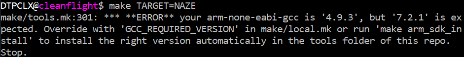
You might get the following error:
make/tools.mk:296: *** **ERROR** your arm-none-eabi–gcc is ‘4.9.3’, but ‘6.3.1’ is expected. Override with ‘GCC_REQUIRED_VERSION’ in make/local.mk or run ‘make arm_sdk_install’ to install the right version automatically in the tools folder of this repo. Stop.
More about the error.
https://github.com/cleanflight/cleanflight/issues/2791
https://github.com/betaflight/betaflight/issues/1424
If you do indeed get the error do the following to fix it.
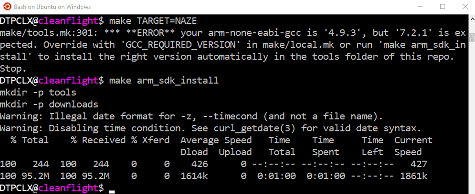
Retry make.
Some messages about missing python might appear.
If so let’s install python…. just to be sure.
Clean the previous make.
Make again.
Data about the build is given at the end of the compilation after running make.
Moded or custom build flash size(text+data) is recommended to be kept smaller than the original build.
Same goes for (static)RAM usage(data+bss).
Source: https://github.com/cleanflight/cleanflight/blob/master/docs/Customized%20Version.md
Firmware .HEX file is now located in the obj folder.
If you are using ubuntu subsystem in Windows 10, do the following to get .hex file to your windows desktop.
Or you could just use file explorer to access it.(not recommended by Microsoft)
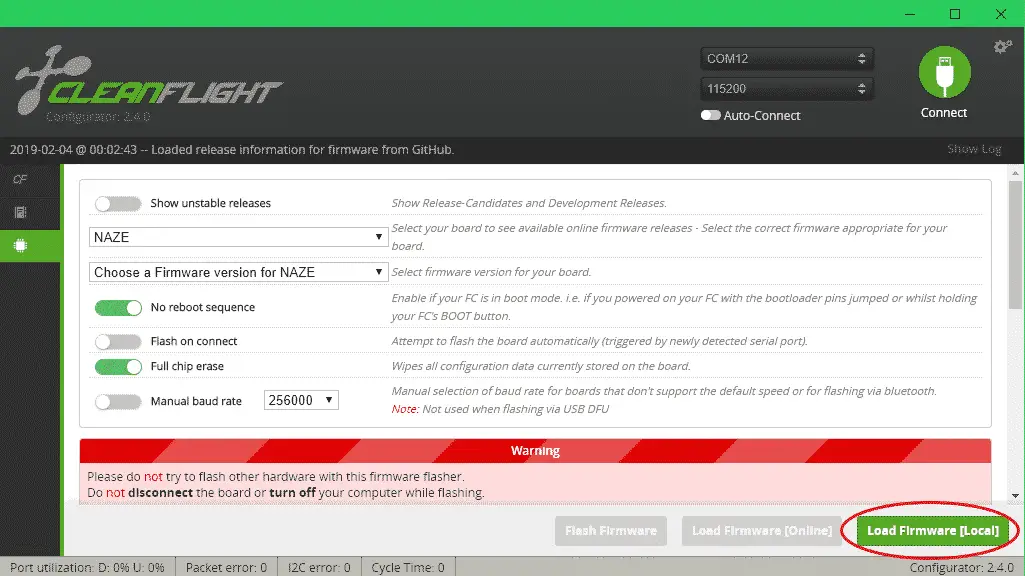
In Cleanflight choose the .hex file you just compiled and flash it.
In this tutorial, we only compiled the firmware. If you want to know how to modify it by adding/removing features check out this post I made.
About
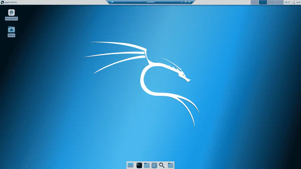
This post covers the installation of a GUI for Kali Linux running on WSL(Windows subsystem for Linux). A quick note if you are looking for Linux with a GUI this might not be the best solution. Depending on your wants and needs it might be a good idea to take a look at running a virtual machine or dual booting(or maybe just installing Linux on your machine).
This tutorial only covers the GUI installation. I am assuming that you already installed Kali. If you haven’t I have a tutorial here that goes over installing WSL and Linux on your computer.
WSL GUI Instalation for Kali Linux
Old (Doesn't work anymore)
The Other Way To Install XFCE
First update your system.
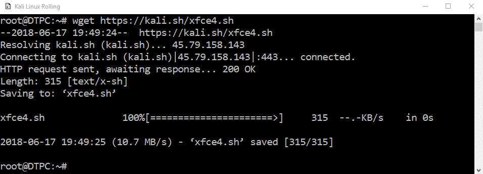
Install xfce.
Install xrdp.
Once the install is complete you will need to start xrdp by typing:
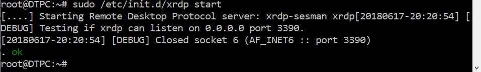
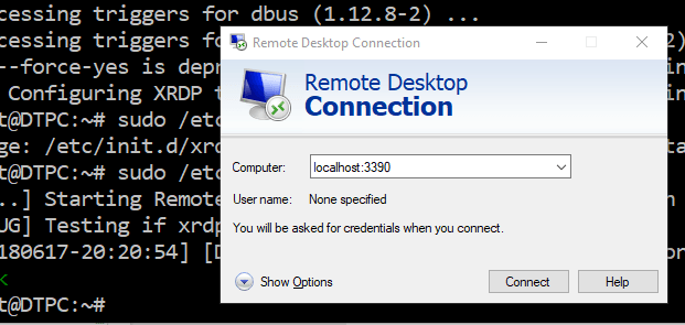
Once starting xrdp all that’s left to do is to connect to Kali. The machine is running on localhost so the IP to connect to is localhost:3390 (with port 3390). I will use the remote desktop connection program that comes with Windows.
Type in the username and password.
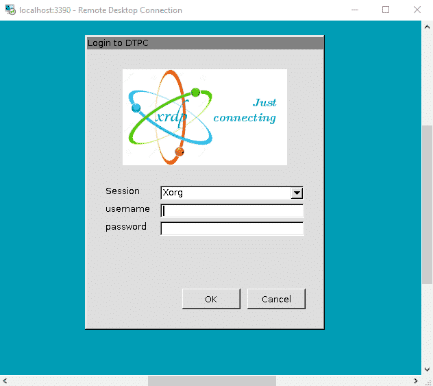
And here is our GUI.
Possible Problem
If xrdp is running on port 3389 and not on port 3390 you will get this error:
Your computer could not connect to another console session on the remote computer because you already have a console session in progress.

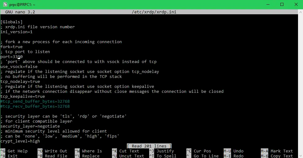
To fix this error you need to change the port. To do so open up the xrdp configuration file:
Change the port=3389 to port=3390 and save the file.
After changing the config file xrdp has to be restarted.
After xrdp has restarted you can try to connect again.

What?
In this tutorial, we’ll be installing Linux on our Windows machine, by using the WSL feature(no VM or dual booting required). WSL(Windows subsystem for Linux) is a Windows 10 feature that provides you with a Bash shell, which you can use to execute Linux commands and run Linux applications.
Why?
I needed Linux to compile the firmware for my quadcopter as the tools aren’t available for Windows. I use Windows as my main OS, but sometimes I do things that require Linux. WSL isn’t quite like having a proper Linux machine set up, but for me, it does seem to do the job most of the times.
More about WSL.
How?
Here is quick, straight to the point tutorial on how to set it all up.
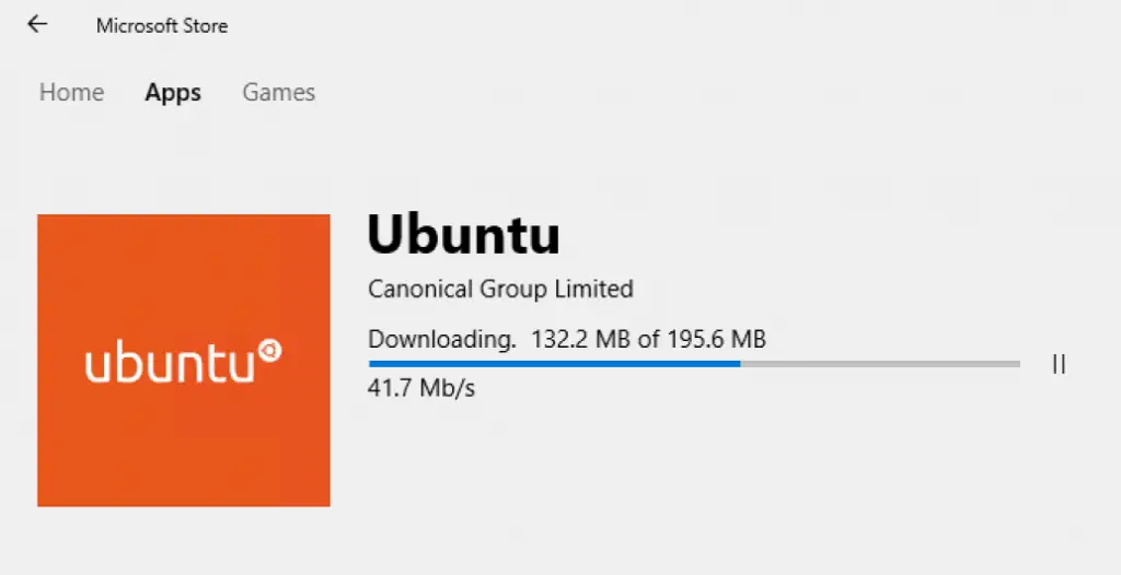
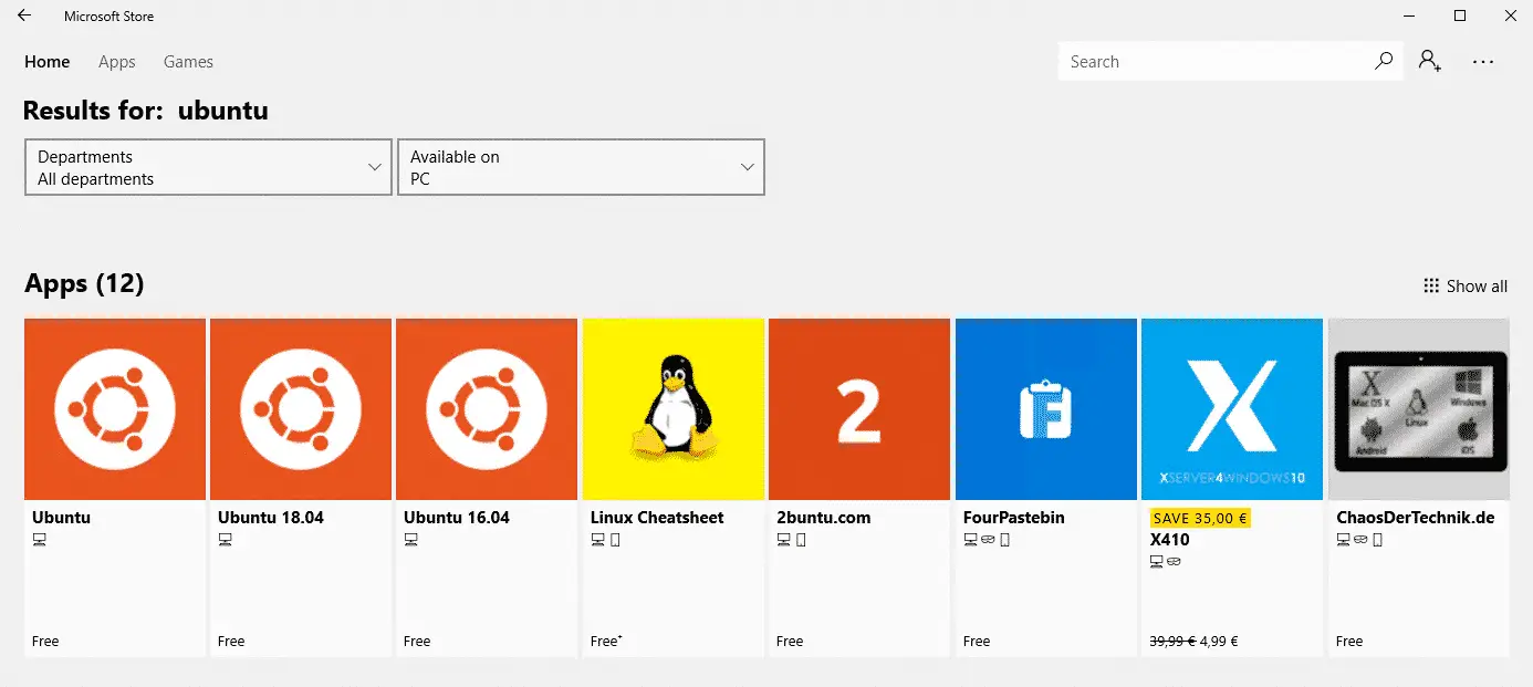
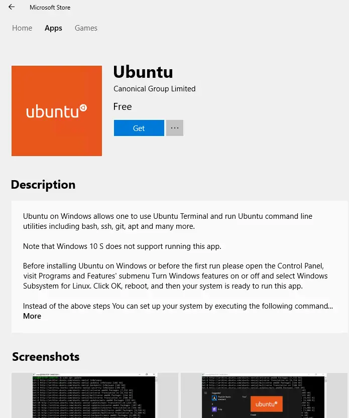
First, go to the Microsoft store and search for Ubuntu. We’ll go with Ubuntu but you can experiment with other distribution available on the MS store. Just search for “Linux” and see what else is available.
Click get, wait for it to install and launch it.

Most likely you will be greeted with the following error: wslregisterdistribution failed with error: 0x8007019e. To fix this we need to enable the WSL(Windows subsystem for Linux) feature.
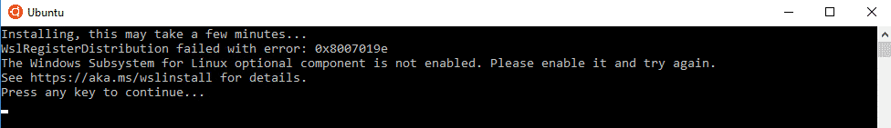
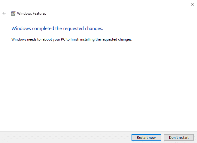
To do so, go to Windows features.
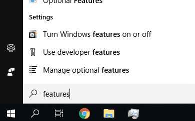
Tick the Windows subsystem for Linux option.
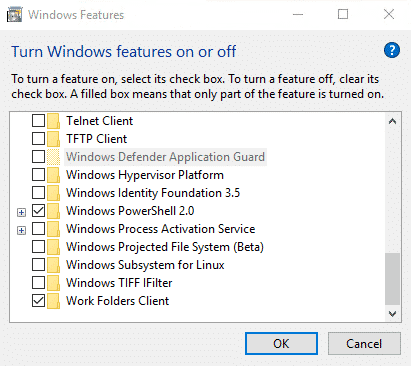
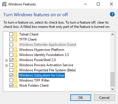
Click OK and wait for it to install. After a quick install, you will be prompted to restart your computer.
After rebooting retry opening Ubuntu. If everything went right Linux should be getting installed automatically. After everything is done installing you will be prompted to create a user account
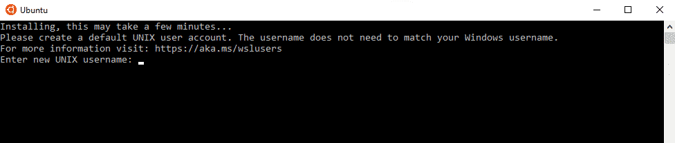
Enter a username and password.
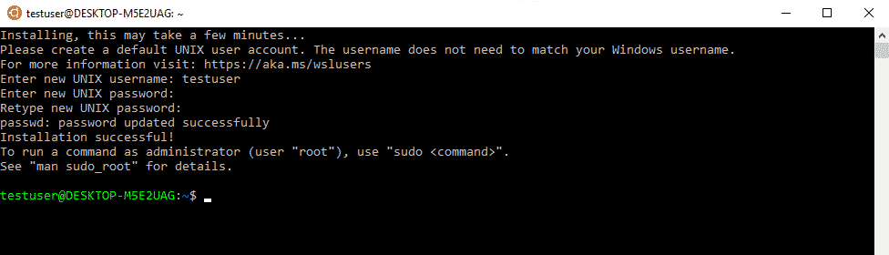
After that, your Linux installation should be ready to go.
Exchanging Files
At some point, you will probably need to exchange some file between Windows and Linux. One way of doing that is going to the Linux installation folder with windows explorer. You can find the Linux install location at: C:\Users\”Windows User”\AppData\Local\lxss
But using file explorer to access the Linux installation folders isn’t the best way of doing things. Instead, you should be using the following method to copy and move files.
sudo cp /(file path) /(destination directory)
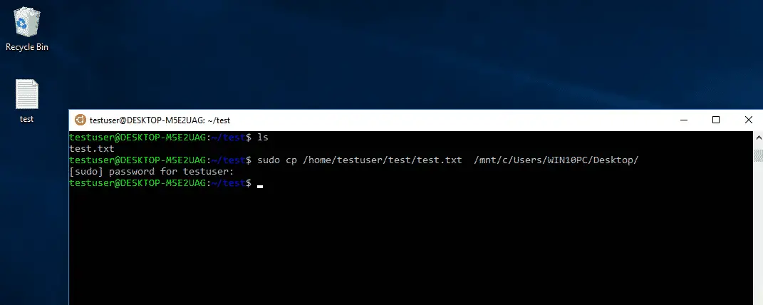
Sudo is used to give root permissions to non-root users. That is also why I was prompted for the password. The cp command copies the file specified in the first path to the location specified by the second path. The windows C: drive is located in the /mnt directory. If you would want to move the file instead of copying it just use the mv command in place of cp.
Note
WSL is not really meant to include a GUI(graphical user interface), but you can install it if you feel like it. Check out how to do it here.