iCE40 FPGA iCE aStick with IceStorm Tutorial

Lattice iCE40 FPGA IceStorm Tutorial

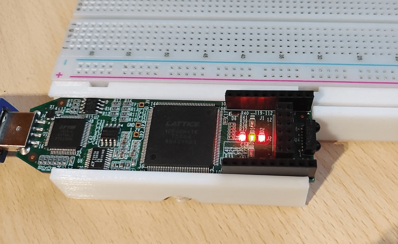
This tutorial will cover the hardware and software setup for the icestick development board that uses an iCE40 FPGA. The IceStorm open source toolchain will be used for programming the board instead of the vendor tools. For the demonstration, we’ll make a simple binary counter that will display its value with the onboard LEDs. The logic design will be defined/coded with Verilog.
ALU the A and B Registers

8-Bit Computer ALU And The Flags Register

In this post, I will talk about the ALU and the flags register of my 8-bit computer. The arithmetical logical unit(ALU) is where all the computation happens in a computer. The ALU of this computer is very simple and only has the option to add or subtract numbers. So something like multiplication would have to be implemented in software.  The flags register stores the Carry(a carry occurs) and Is Zero(the result is a zero) flags that it receieves from the ALU. 

button debounce module

8-Bit Computer Button Debouncing

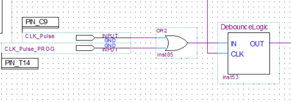
In this post, we’ll take a look at the button debounce module of my 8-bit computer. Ben used a 555 timer in his clock module to make a delay to debounce the button. I took a different approach. I took the 50 MHz input from the crystal oscillator and lowered the frequency by using another clock module. This way I have another slower clock signal independent from the main clock. This slow frequency is then fed into the debounce modules.

clock module

8-Bit Computer Clock Module

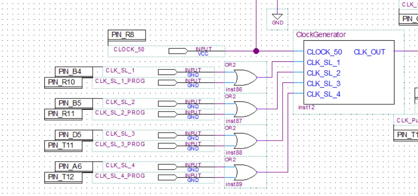
In this post, we’ll take a look at the clock module of my 8-bit computer. Ben used a 555 timer in his clock module to generate the clock signal for his breadboard computer. The approach I took is a bit different. The DE0 Nano FPGA development board has an onboard 50 MHz crystal oscillator connected to one of the pins of the FPGA. This is where we can get our clock signal from. The problem is that the frequency is way too high for the computer and needs to be lowered. This can be accomplished by dividing the frequency using a frequency divider(which is esentially just a ripple-carry counter) or by using a PLL(phase locked loop).

program counter ripple carrycarry

8-Bit Computer Program Counter

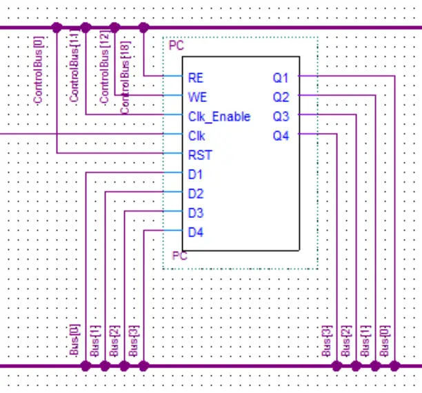
In this post, we’ll take a look at the program counter of my 8-bit computer. The PC(program counter) is used to store the memory address of the next instruction to be executed. After the instruction was executed it the value in the PC will be incremented by one, therefore, pointing at the next memory address that contains the next instruction. The PC is almost identical in construction to the microinstruction counter as both of them are just ripple-carry counters.

control unit and microinstruction counter

8-Bit Computer Control Unit

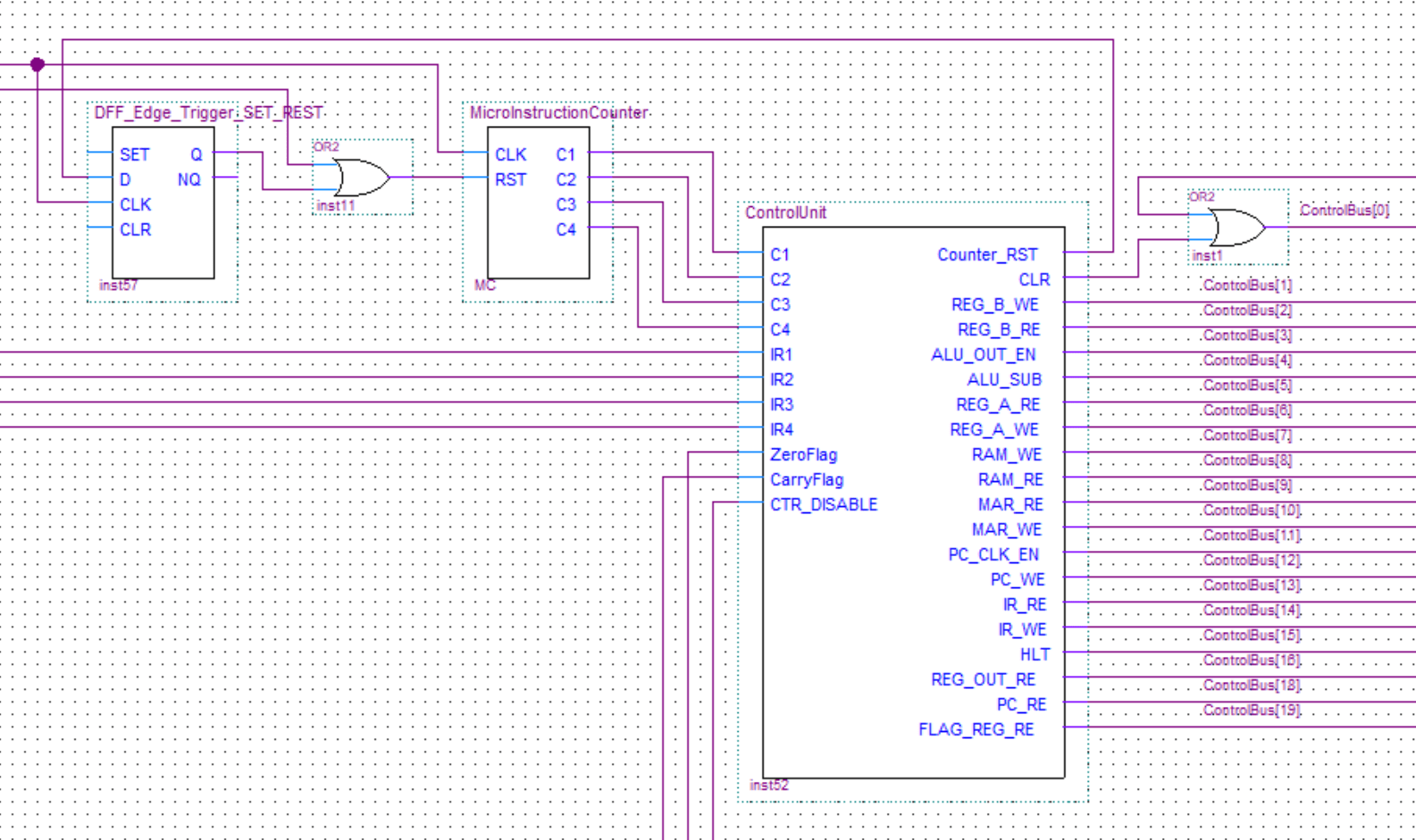
In this post, we’ll take a look at the control unit of my 8-bit computer. Ben used an EEPROM to make the control unit in his computer. This is a quite clever approach if you are building your computer on a breadboard as it drastically decreases the complexity, amount of components and space needed. But in my case, it was much easier to just implement the control unit using discrete logic gates. 

RAM

8-Bit Computer RAM

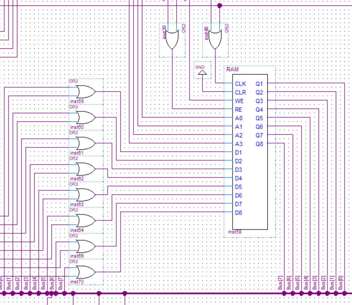
In this post, I will describe how I implemented the RAM in my 8-bit computer. The RAM size is very small, 16 cells(words) each one with 8 bits. It’s a small and simple computer so a program and its variables will be directly loaded into memory using a programmer. Results and any temporary variables are also all just stored in RAM. The only exception is if you want to output a value you can directly load it into the output

encoder and decoder

8-Bit Computer Encoders and Decoders

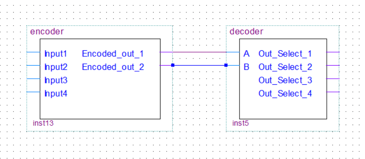
In my 8-bit computer build, I only used decoders. However, I will still cover encoders in this post for the sake of completeness. You can see the decoders being used in the RAM, multiplexers, and the control unit of the computer. Decoders decode the binary value on the input to an individual selection on the output. The encoder will of course do the exact opposite.

In this post, we’ll take a look at encoders/decoders with 4 inputs/outputs because it’s easier to understand how they work. The logic is the same for more inputs/outputs, the logic circuit just gets scaled up.

quartus multiplexer

8-Bit Computer Multiplexer and Demultiplexer

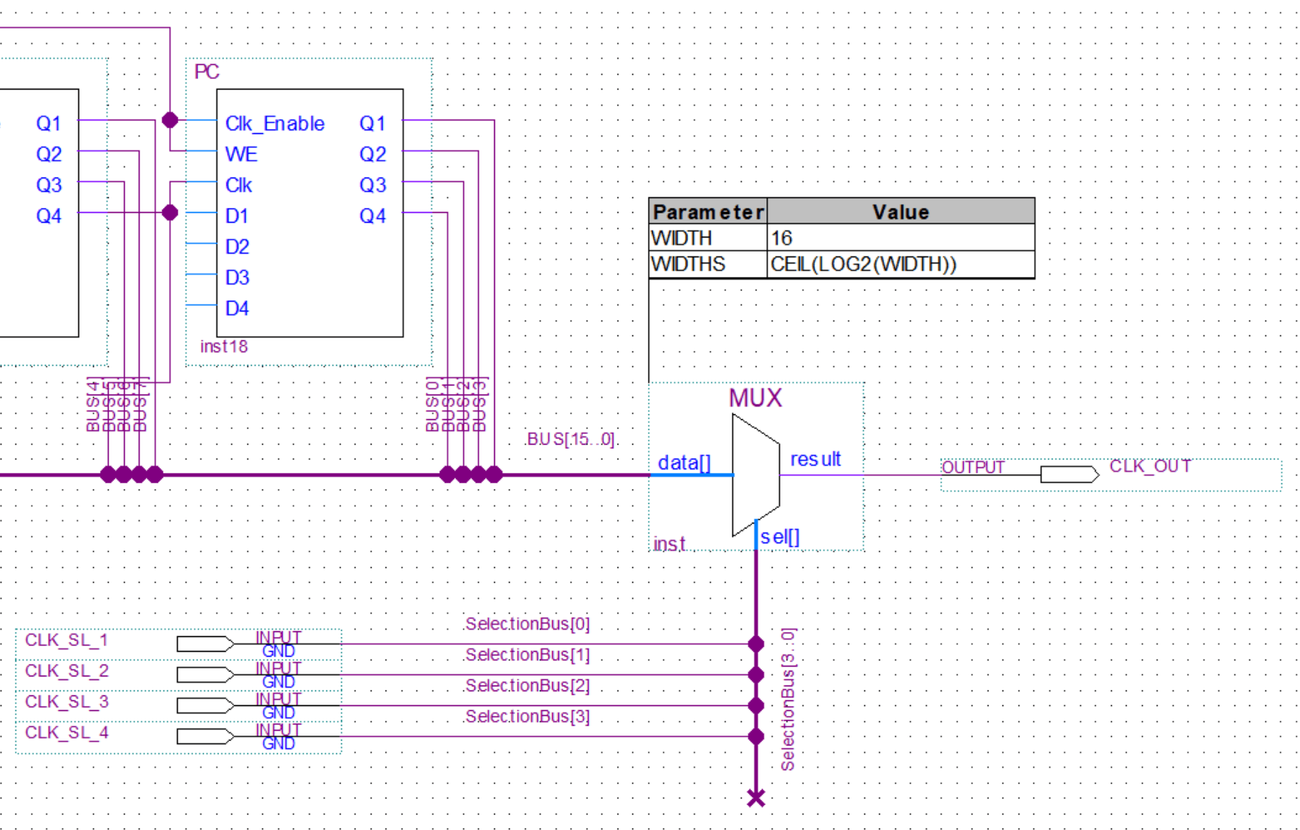
In this post, we’ll take a look at multiplexers and demultiplexers. In my 8-bit computer build, I only used multiplexers, you can see them being used in the clock generation circuits. I will however still cover demultiplexers in this post for the sake of completeness. Multiplexers are used to select one of the multiple inputs and output it to one common output. Demultiplexers do the opposite of that and take in one input and put it out through one of the multiple outputs that was selected. Let’s just take a look at the brief explanations and schematic bellow for a better understanding.

Advertisment ad adsense adlogger