18650 Battery Charge Shield UPS Modification

mod schematic bottom
Share:

About

In this post, I will show you how to modify the UPS so it works properly. Years ago I bought these 18650 battery charge shield boards that can be essentially used as a UPS(uninterruptible power supply). I just recently made a project that required a UPS so I finally decided to use them. This is when I found out about all the problems associated with this module.

Hardware used:

About The 18650 Battery Charge/UPS Shield

One might think that you could simply use a power bank as a UPS by hooking up the power to the charge port and then connecting the load to the output. The thing is that this won’t work because the power bank will stop outputting power when you start to charge it. Additionally, if the current draw of the load is too small most power banks tend to shut off.

A UPS should connect the load directly to the power source until it goes out(depending on the type of UPS line interactive, double conversion, standby, …). When that happens the UPS should switch to powering the load from its internal battery until the power returns upon which it should change back to powering the load from the power source and start recharging its internal battery.

There are a few boards out there advertised as being able to do that. The board we are talking about in this post can usually be found on eBay, Aliexpress or Amazon under a name like “18650 Battery Charge Shield V3 for Arduino, Raspberry Pi, ESP32/8266” or something along these lines.

This board however has quite a few design flaws:

    • The power switch is placed on the output instead of being placed in series with the battery. This means the DC-DC converter is always on thus draining the battery.
    • The battery might get power cycled if the current being drawn is too low.
    • The battery might be getting overcharged.

Here are some videos outlining the problems:

    • Andreas Spiess made this and this video regarding this UPS board.
    • This video here also talks about the issues and does the same modification we’ll be doing.
    • bigclivedotcom made this video regarding the TP4056 charging chip clearing some misconceptions about it.

So from what I gather, there should be no overcharging safety issue but your battery might be getting power cycled between 4.1V and 4.2V if your load draws very little current(less than 100mA) which causes the charger to shut off. This is why I nonetheless added the diodes.

A power switch still needed to be added between the battery and the rest of the circuit to save battery life. Otherwise, the DC-DC converter will always stay powered on wasting battery even when we don’t need to power our load.

Note: I cut off part of the PCB and added a micro USB connector so the UPS module would fit inside a case(see it in my project here). You don’t need to do that.

18650 Battery Charge Shield Modification

This is the original unmodified board.
This is how you should modify the board.
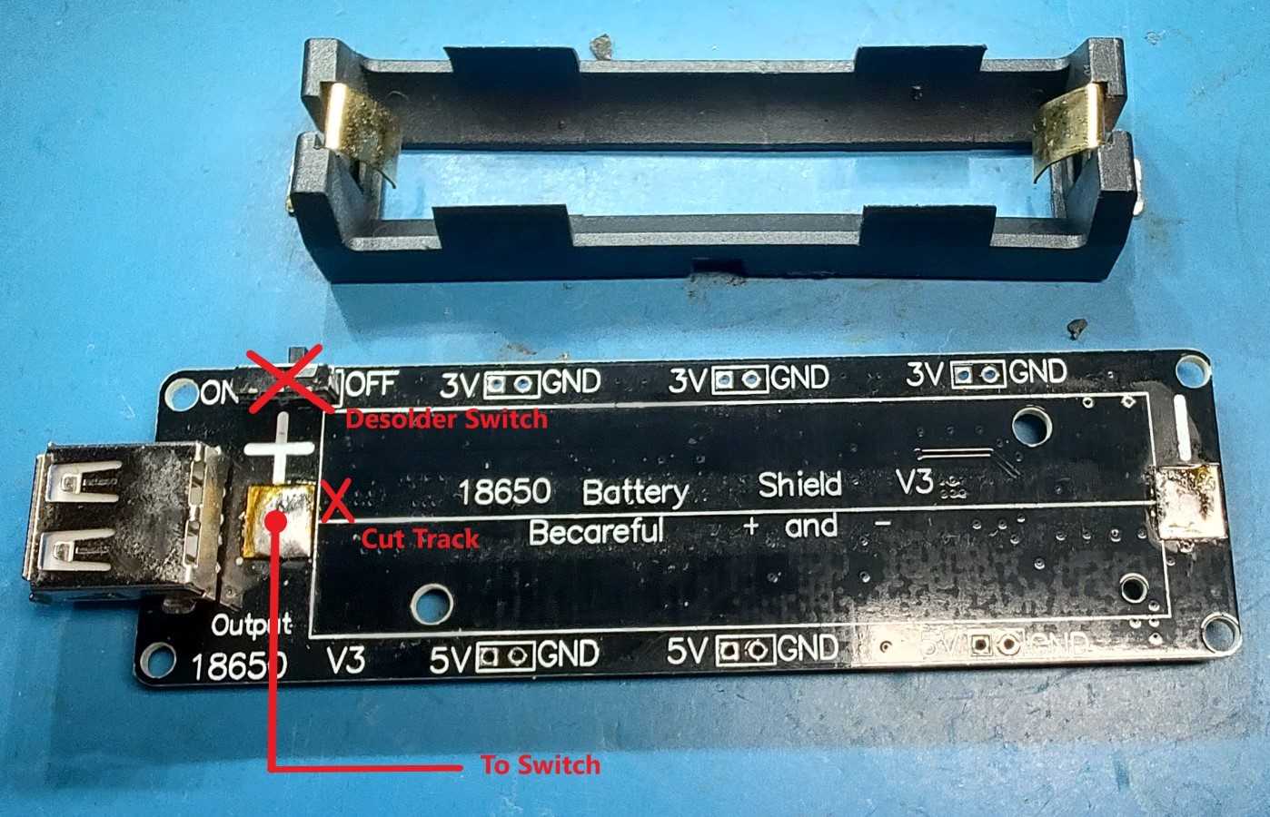
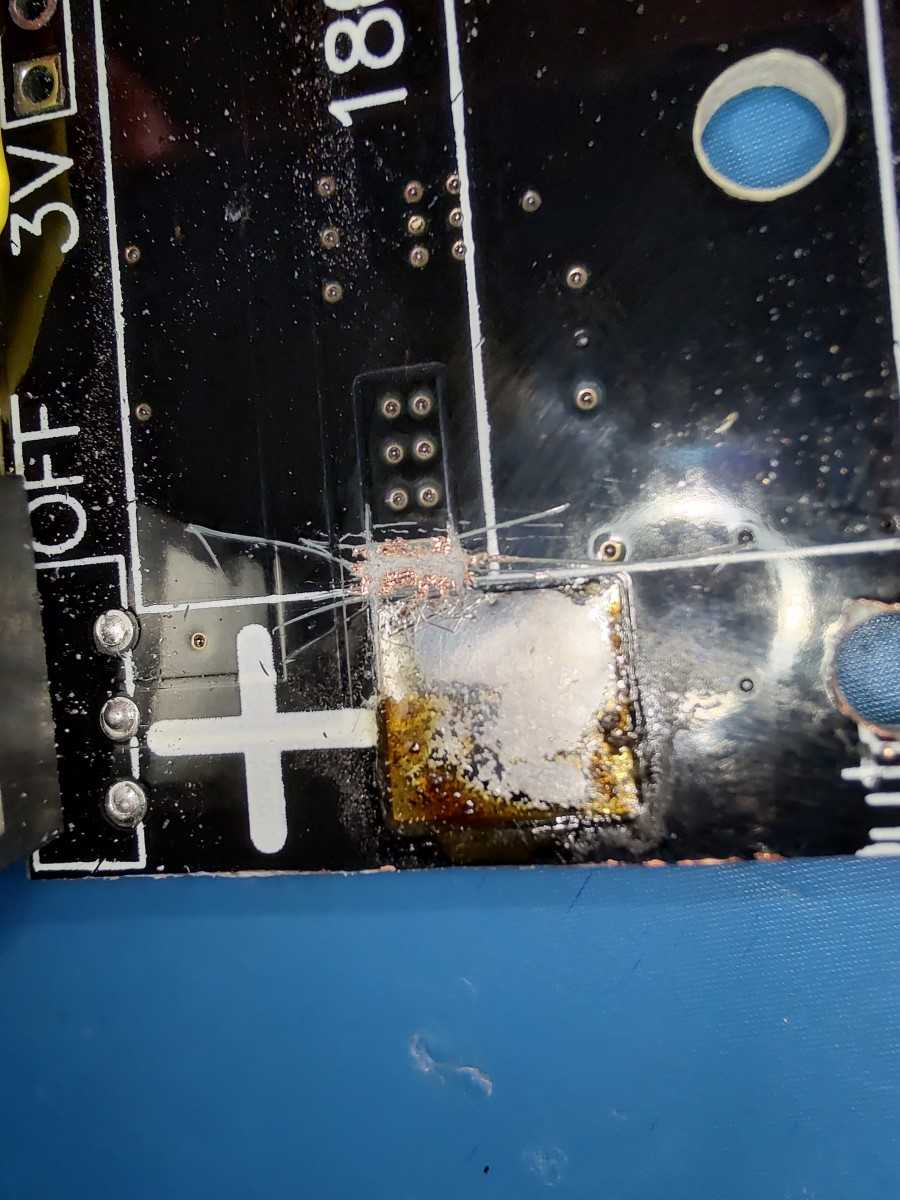
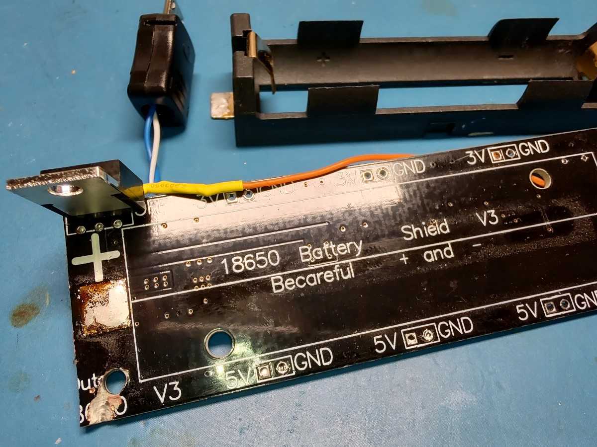
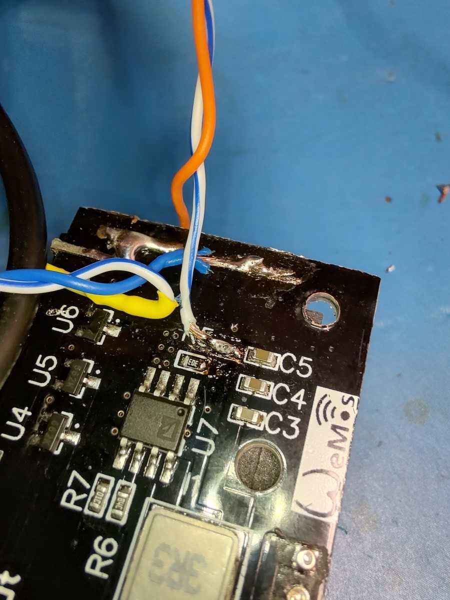
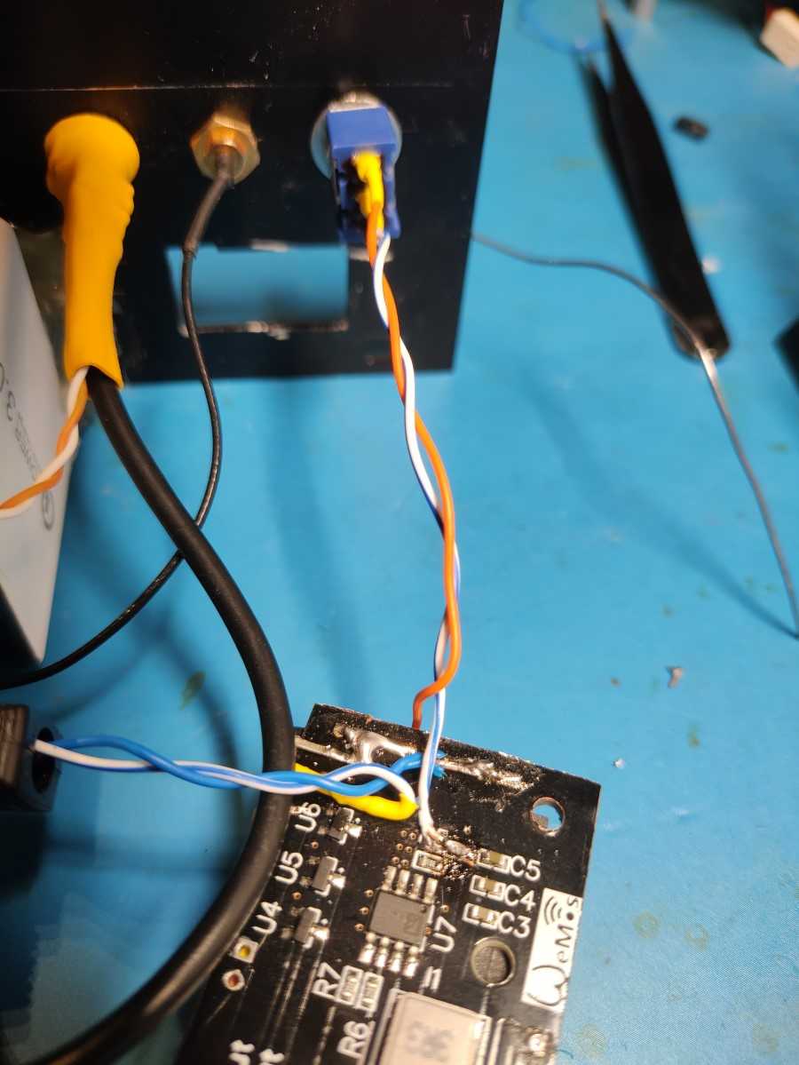
First, desolder the 18650 battery socket so you can get access to the PCB beneath. You can also desolder the switch as it won’t be used. Cut the PCB track and re-solder the socket back on. Then solder one of the wires going to the external switch to the positive terminal/pad of the battery socket.
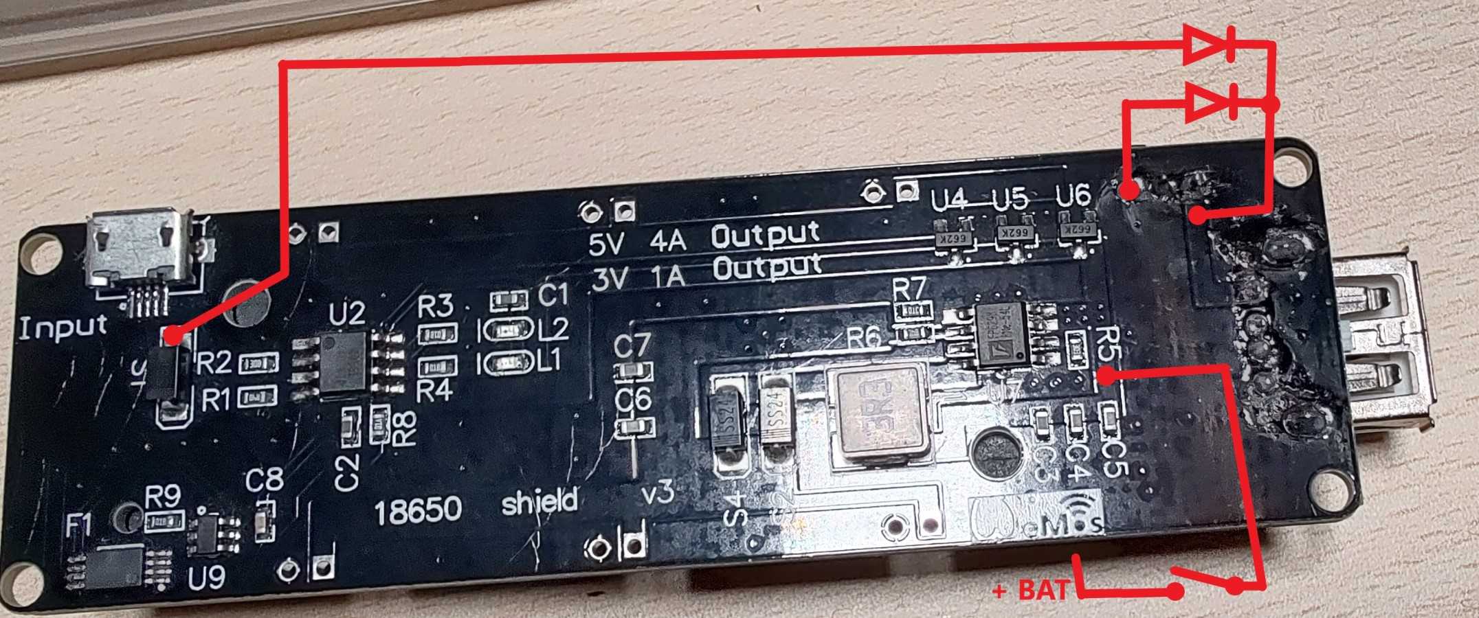
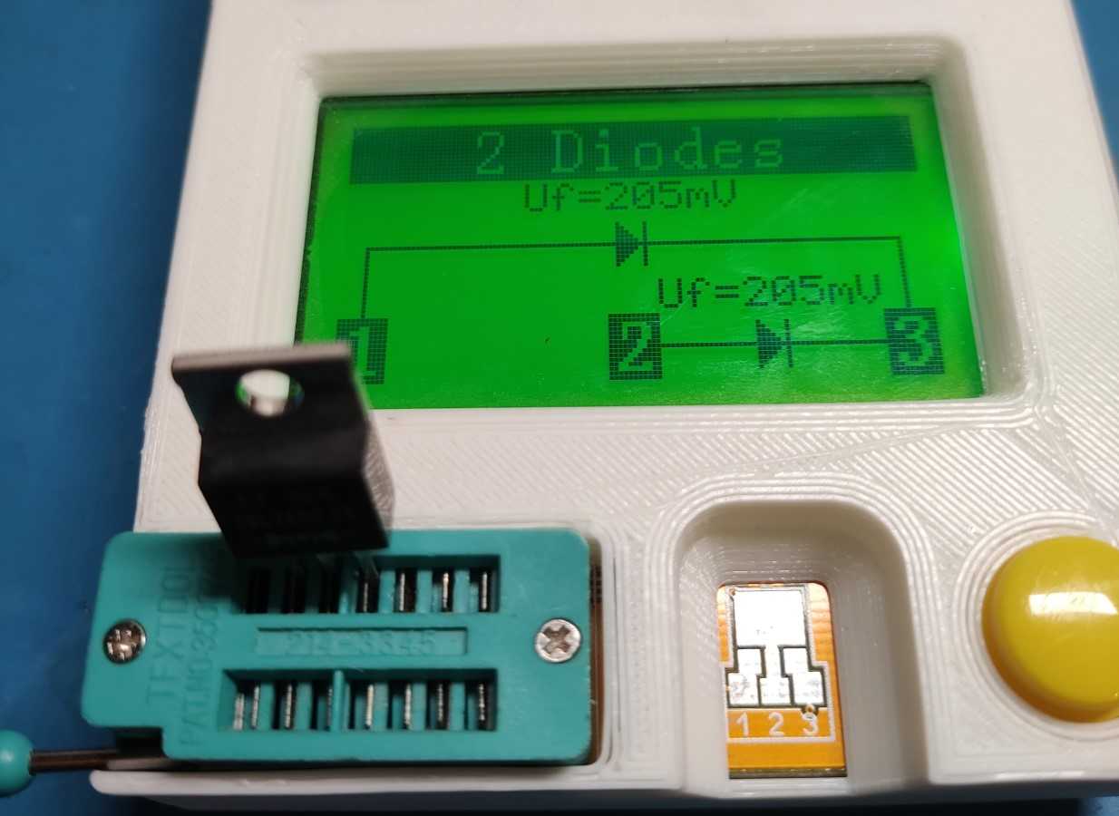
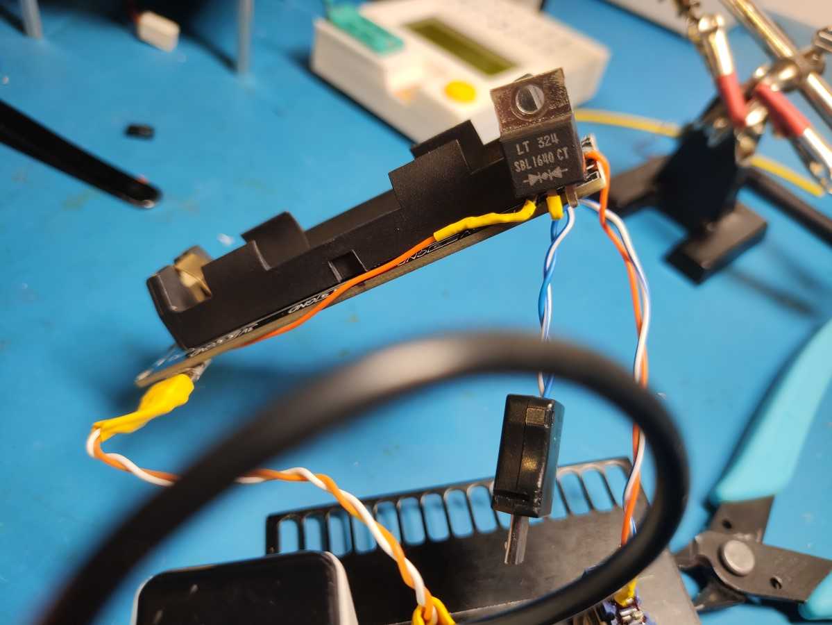
For the diodes, you can use any low drop Schottky diode(1N582x). Instead of using two separate diodes, I used a TO-220 package with two diodes inside as I already had it in my parts bin.
Scrape away the solder mask on the trace next to R5 and solder the other wire going to the power switch.
Here’s how it all looks like in the end.
Share:

Comments

    1. Hi.

      This is the correct way to connect things: https://eecs.blog/wp-content/uploads/2024/01/mod-schematic-bottom.jpg

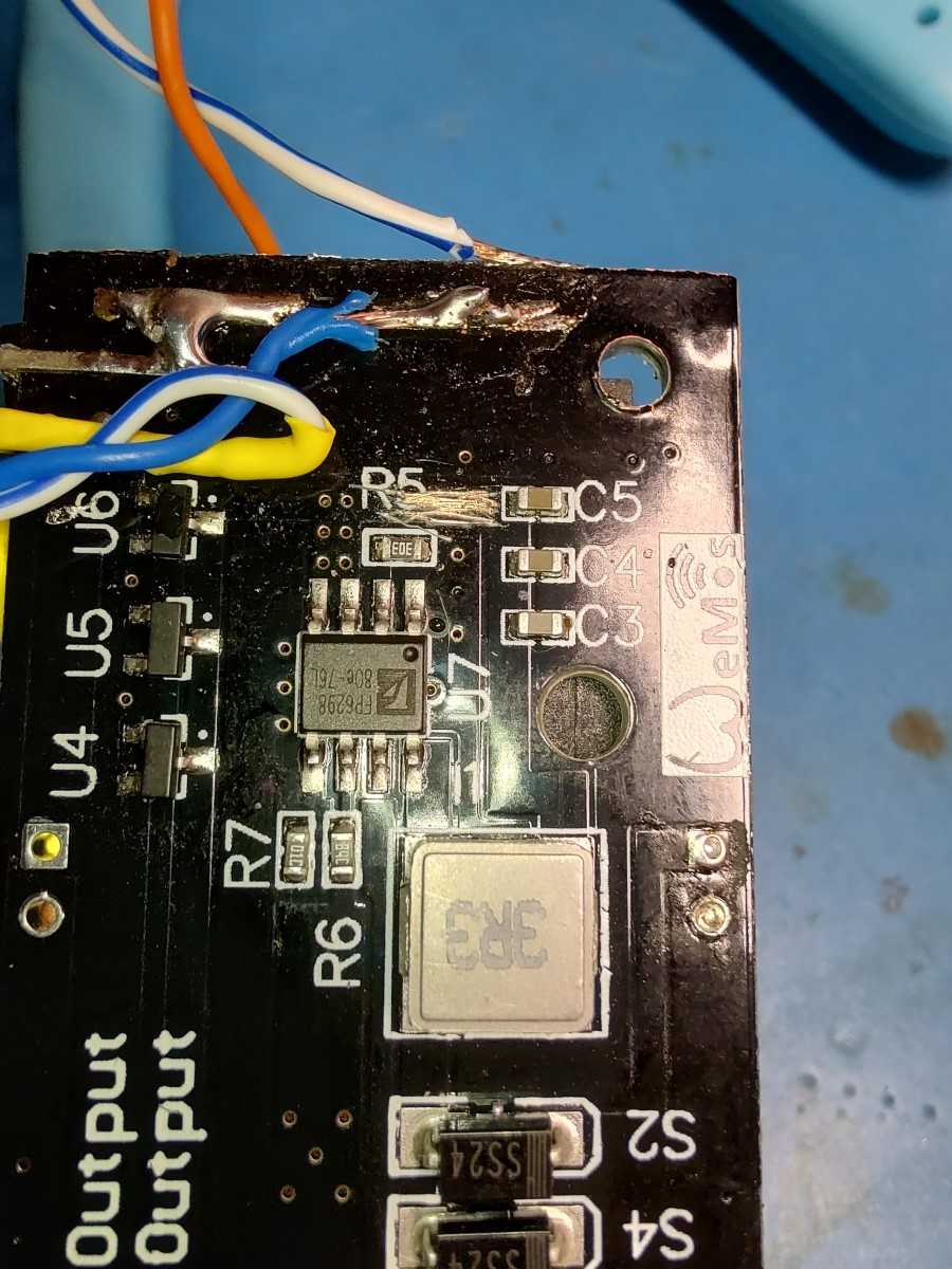
      When you said it’s connected in reverse I assume you are talking about this

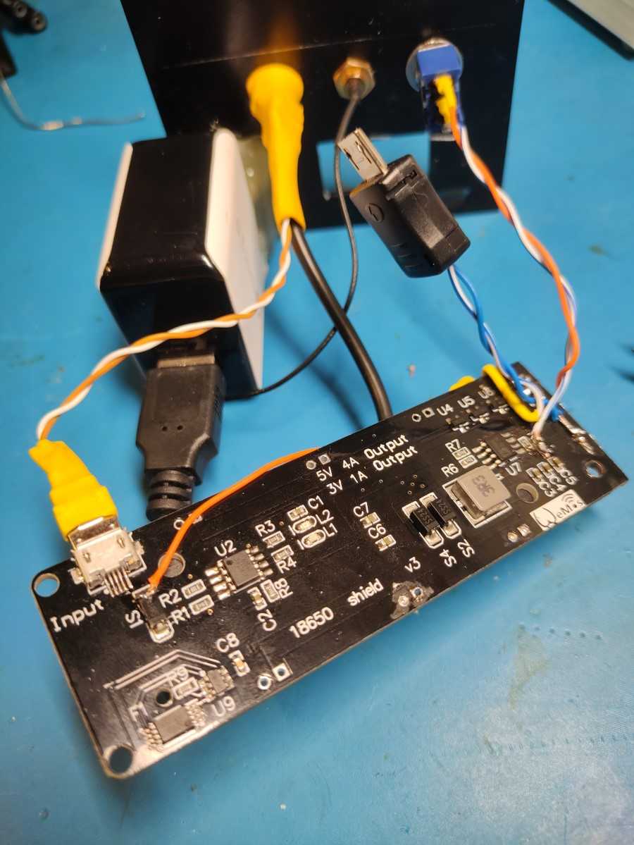
      I did things a bit differently here because I had to cut off the USB connector so the PCB would fit into a case. I bridged the switch and connected the input to the diode to the trace that would go to the USB connector(if I hadn’t cut it off). The output(center pin) from the LT324 then goes directly to the micro USB connector.

Leave a Reply

Your email address will not be published. Required fields are marked *

The following GDPR rules must be read and accepted:
This form collects your name, email and content so that we can keep track of the comments placed on the website. For more info check our privacy policy where you will get more info on where, how and why we store your data.

Advertisment ad adsense adlogger