About
In this post, I’ll show you how to program the Attiny microcontrollers via the Arduino IDE using an Arduino board as an ISP programmer.
Hardware used:
- #adAmazon LinkAttiny
- #adAmazon LinkArduino
- #adAmazon LinkZIF Socket
- #adAmazon LinkPCB Prototype Board
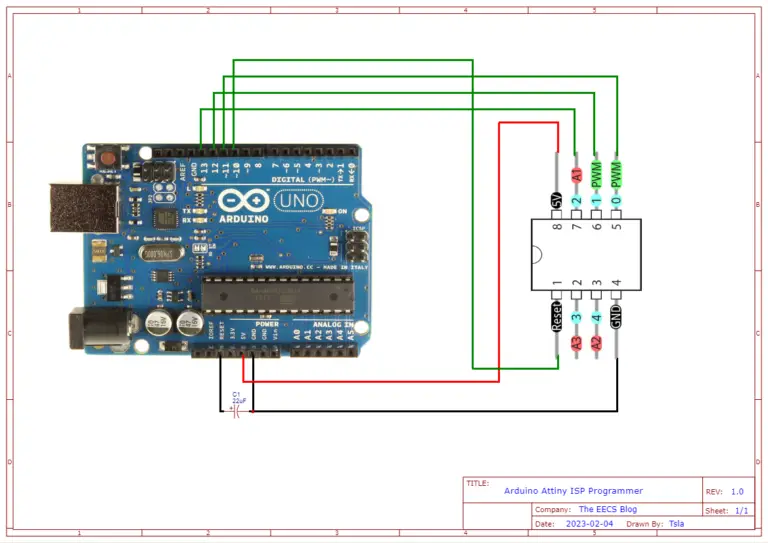
Hardware Connections
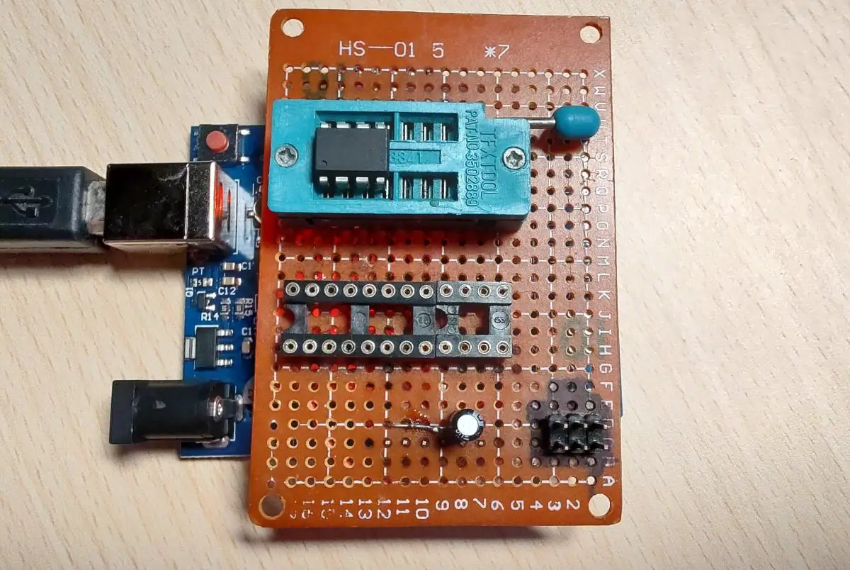
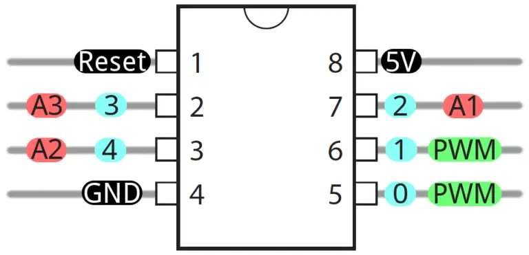
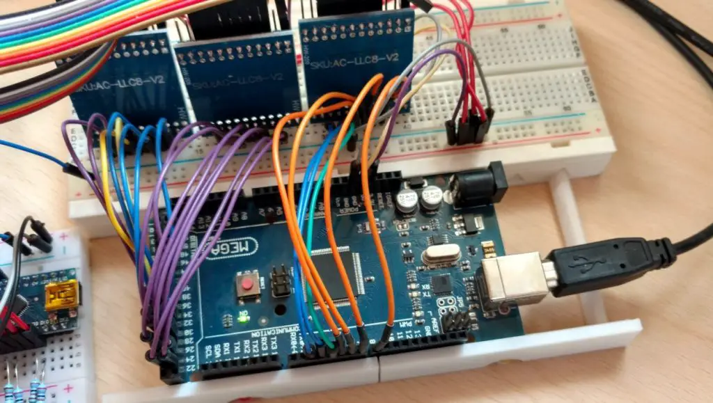
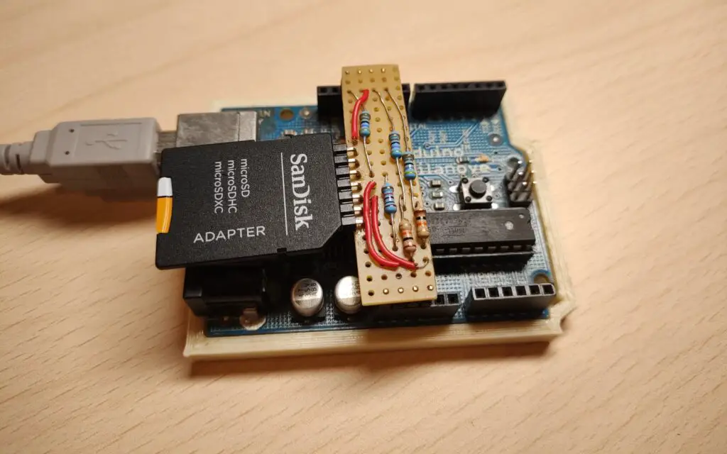
You can make these connections on a breadboard or you can make a shield for the Arduino like I did. A shield will make it much easier the next time as you don’t have to redo all the wiring again. You simply plug in the shield and you are ready to go. I also added a ZIF(zero insertion force) socket to make it easier to insert/remove the attiny chip.
Convert The Arduino Into An ISP Programmer
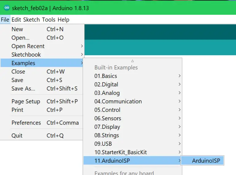
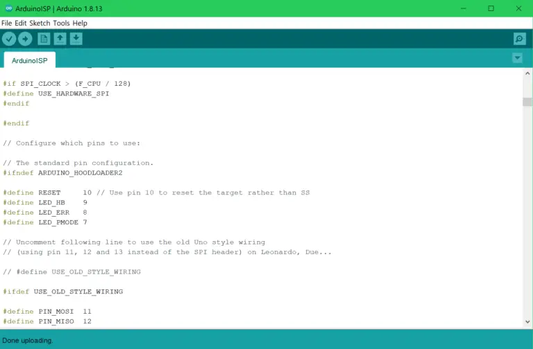
In the Arduino IDE go under Examples -> 11.Arduino ISP and select the Arduino ISP sketch. Upload this to your Arduino and it will now act as an ISP programmer.
Adding Attiny To The Arduino IDE
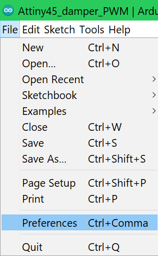
In the Arduino IDE go under File -> Preferences.
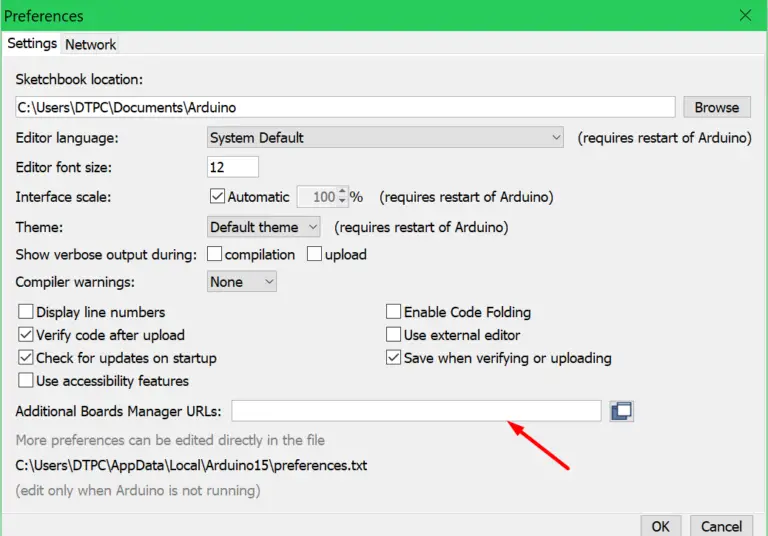
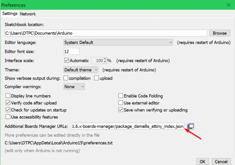
When the Preferences window opens up paste this URL https://raw.githubusercontent.com/espressif/arduino-esp32/gh-pages/package_esp32_index.json into the input box.
Note: If you have a URL from another board added put the ESP32 URL after that one and separate them with a comma like so: your first url,your second url
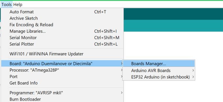
Open the Boards Manager under Tools -> Board -> Boards Manager… Then type esp32 and install the esp32 boards.
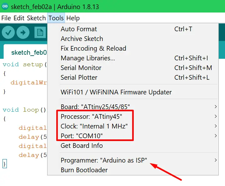
Select your board like so Tools -> Board -> ATtiny Microcontrollers -> “The MCU you are using” and then set the rest of the settings like in the image below(you can speed up the clock if you want):
Note: It’s important you select “Arduino as ISP” for the programmer.
Firmware
This is just a simple blink program we’ll use to verify that we are able to program the Attiny MCU.
void setup()
{
  pinMode(1, OUTPUT);
}

void loop()
{
    digitalWrite(1, HIGH);
    delay(500);
    digitalWrite(1, LOW);
    delay(500);
}
Flashing And Testing
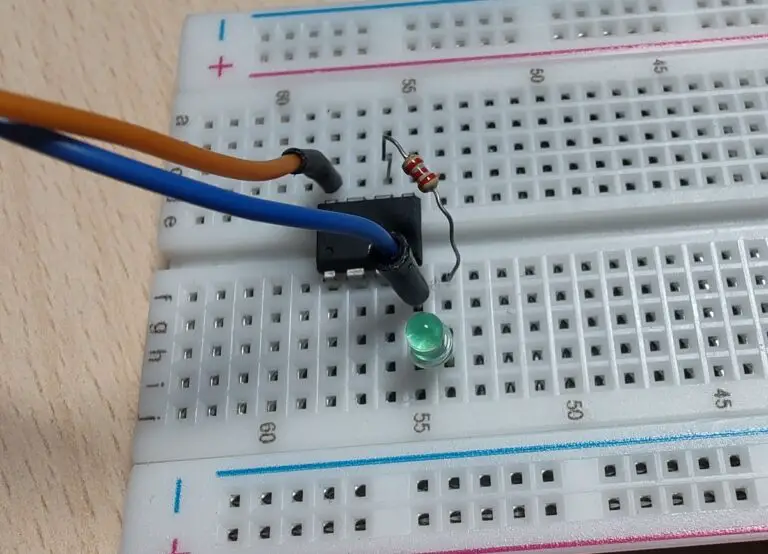
Upload the firmware, put the Attiny into the circuit and if everything went right the LED should be blinking.
