About
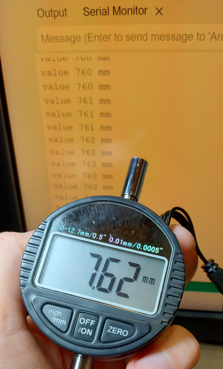
In this post, I’ll show you how to read data from one of those generic Digital Dial Indicators using an Arduino.
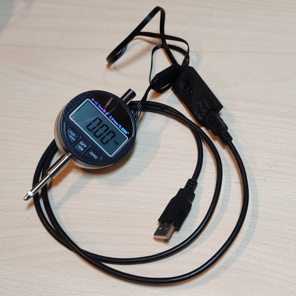
I wanted to map out the bed level of my 3D printer so I thought I could use this digital dial indicator I bought many years ago.
I remembered it had a digital interface I could use to extract the data.
I found a few people already figured out how to read the data out over serial using an MCU:
https://hackaday.io/project/511-digital-dial-indicator-cnc-surface-probe
https://www.davidpilling.com/wiki/index.php/DialGauge
Note: I think the same protocol is used in most of those cheap generic digital calipers as well.
Hardware used:
- #adAmazon LinkDigital Dial Gauge
- #adAmazon LinkArduino Nano
Hardware Connections
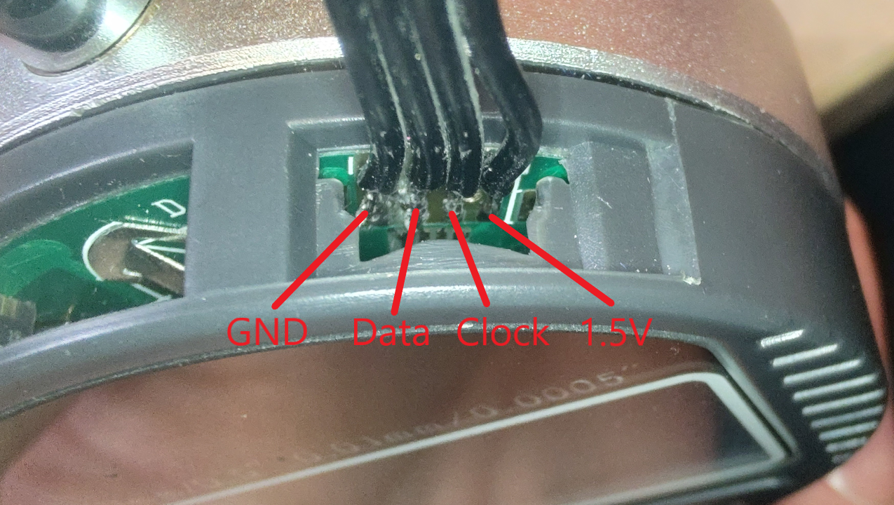
I soldered the wires directly to the pads however if you want a proper connector you can 3D print it from here.
Code
Because the signals are lower in voltage that the Arduino digital pins can detect you would need a small additional amplifier circuit with a transistor to increase the voltage.
I found this code here https://www.davidpilling.com/wiki/index.php/DialGauge that uses the analog inputs instead so we don’t need any extra hardware.
// David Pilling March 2017 #includevoid pr(char *fmt, ... ) { char buf[128]; // resulting string limited to 128 chars va_list args; va_start (args, fmt ); vsnprintf(buf, 128, fmt, args); va_end (args); Serial.println(buf); } void setup_serial(void) { } void setup () { Serial.begin(9600); ADCSRA=0; // ADC Control and Status Register A ADCSRB=(1< =24) { pr("value %d %s",(negative?-outputval:outputval)/(inches?2:1),inches?"in":"mm"); } looptime=millis(); outputval=0; inches=0; negative=0; shift=0; while(1) { ADMUX=0; __builtin_avr_delay_cycles(MUXWAIT); val=(ACSR & (1< TIMEOUT) break; } if((millis()-looptime)>TIMEOUT) break; ADMUX=1; __builtin_avr_delay_cycles(MUXWAIT); val=(ACSR & (1< =24) break; } } }
Result
This is the result in the serial monitor and serial plotter.


