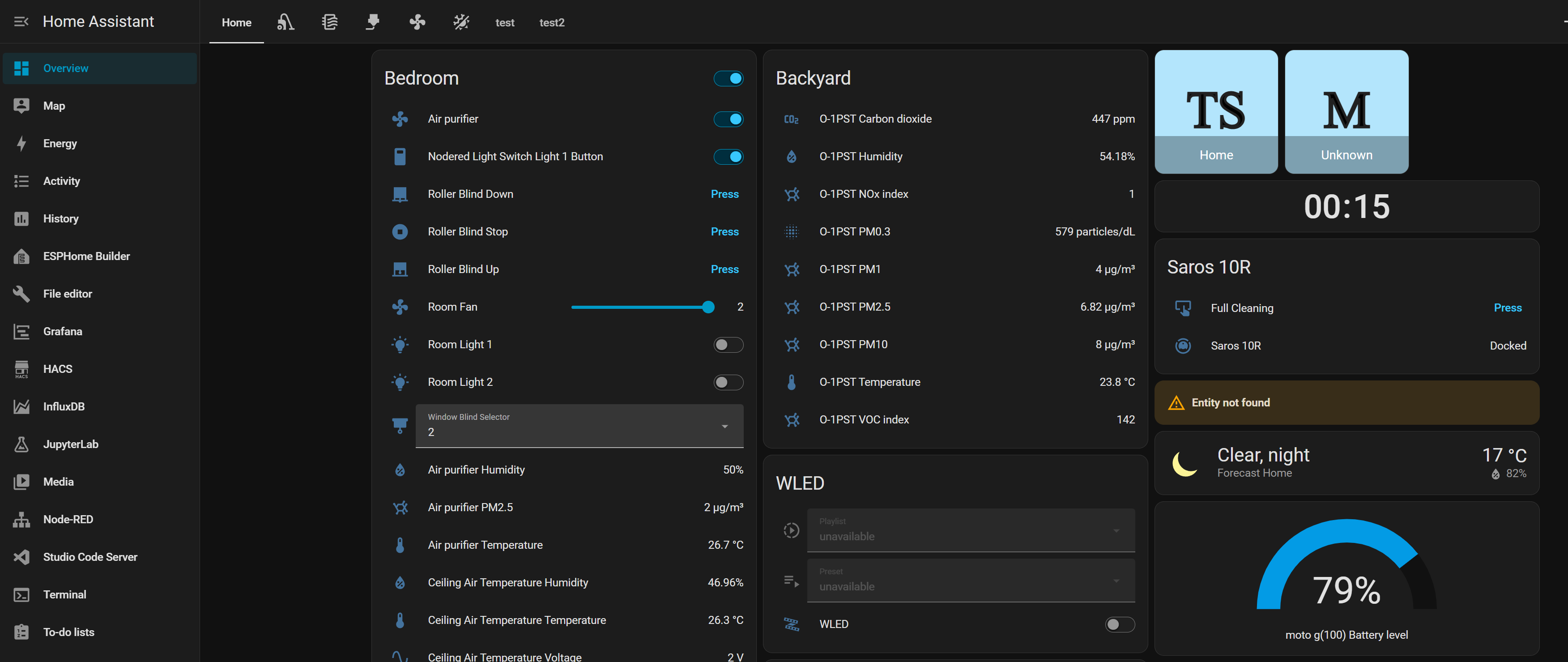
I’ve seen other people’s dashboards and some of them are pretty impressive looking. My Home Assistant dashboard really could use some work. But I’m the only one using it and I kind of got used to. This might be a future project to “beautify” and rearrange my dashboard.
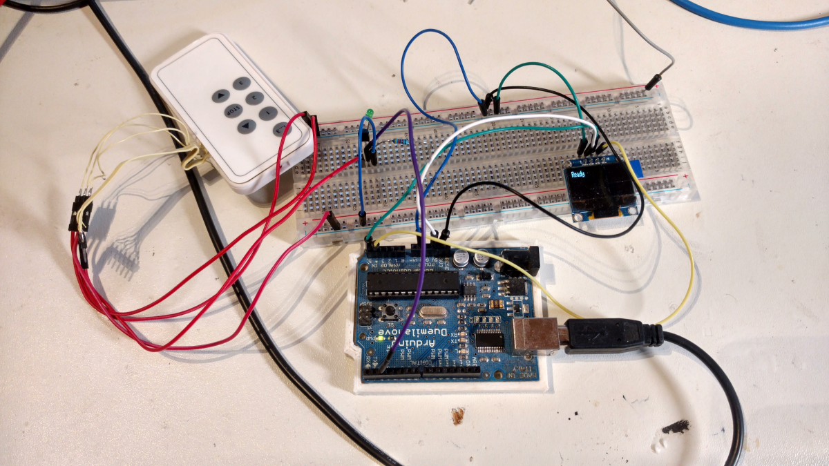
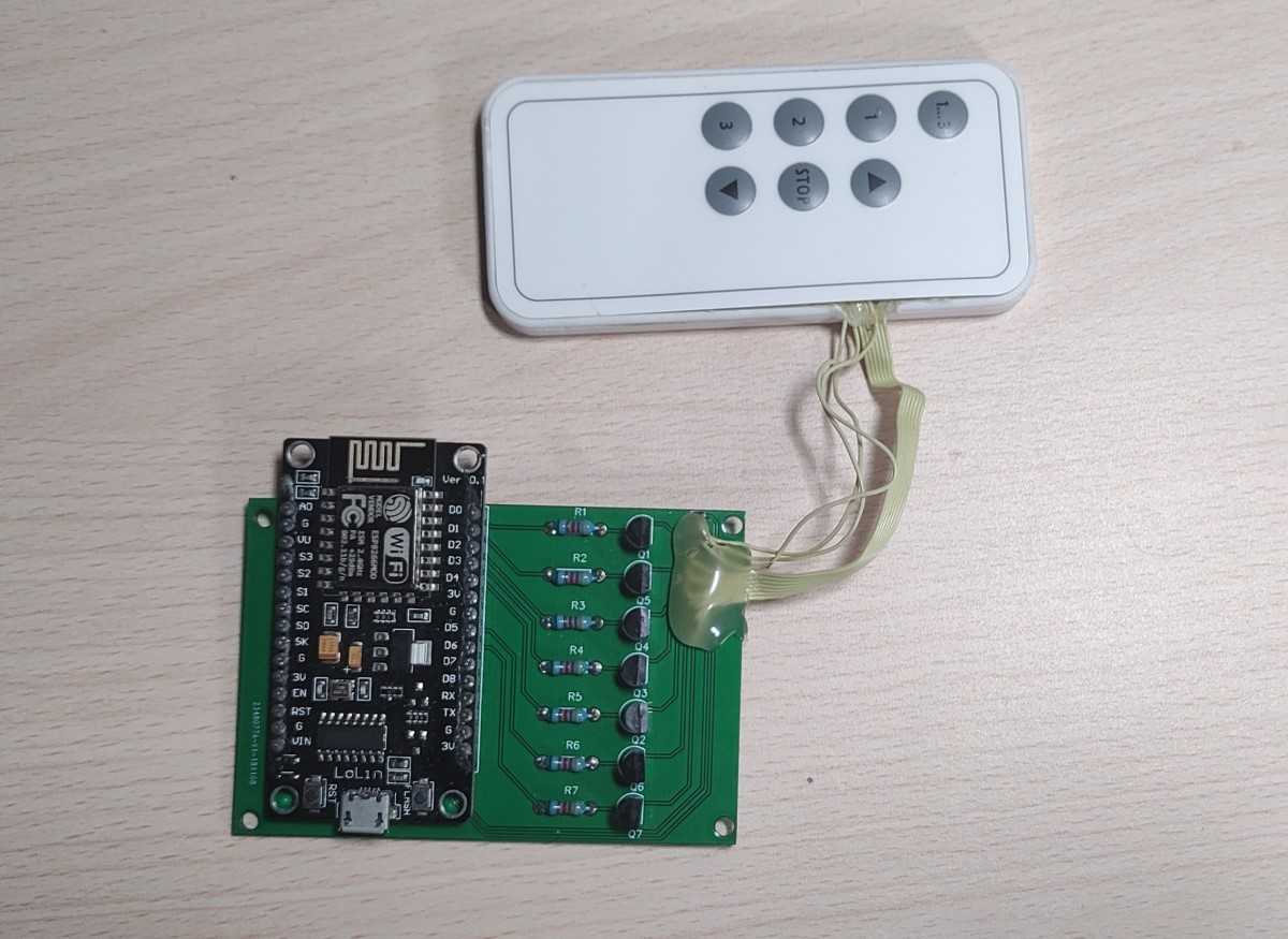
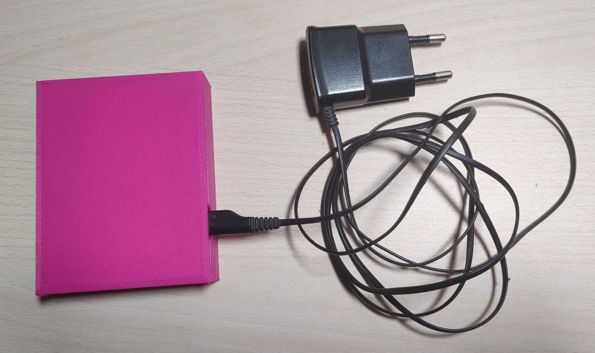
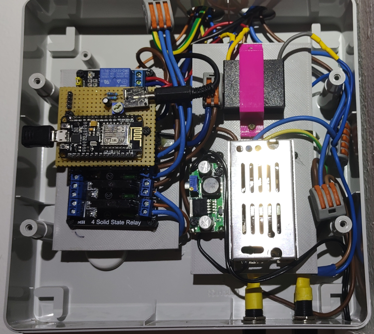
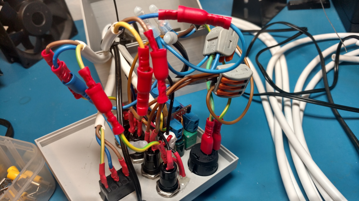
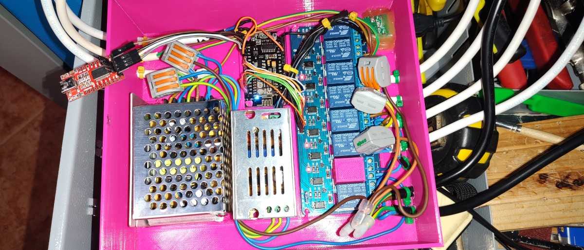
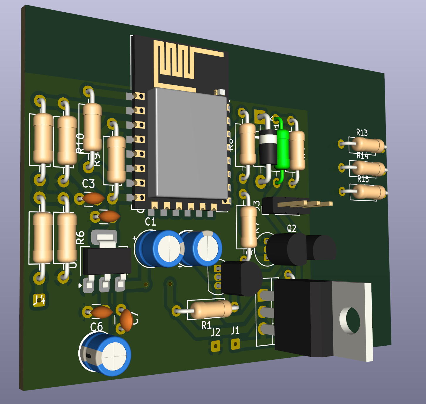
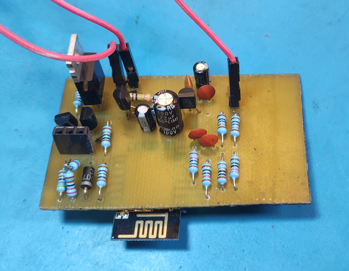
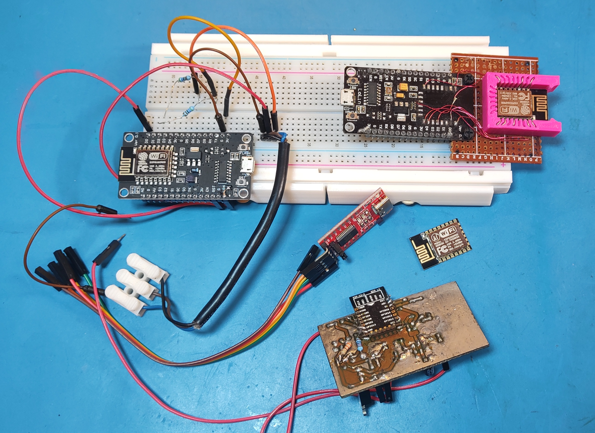
As I said in the beginning, I later switched to an ESP8266. At that point, I also made a simple PCB with a few transistors to simulate button presses. I had put everything into this simple 3D printed enclosure for a while before recently shoving it into the electrical box with a bunch of other stuff.
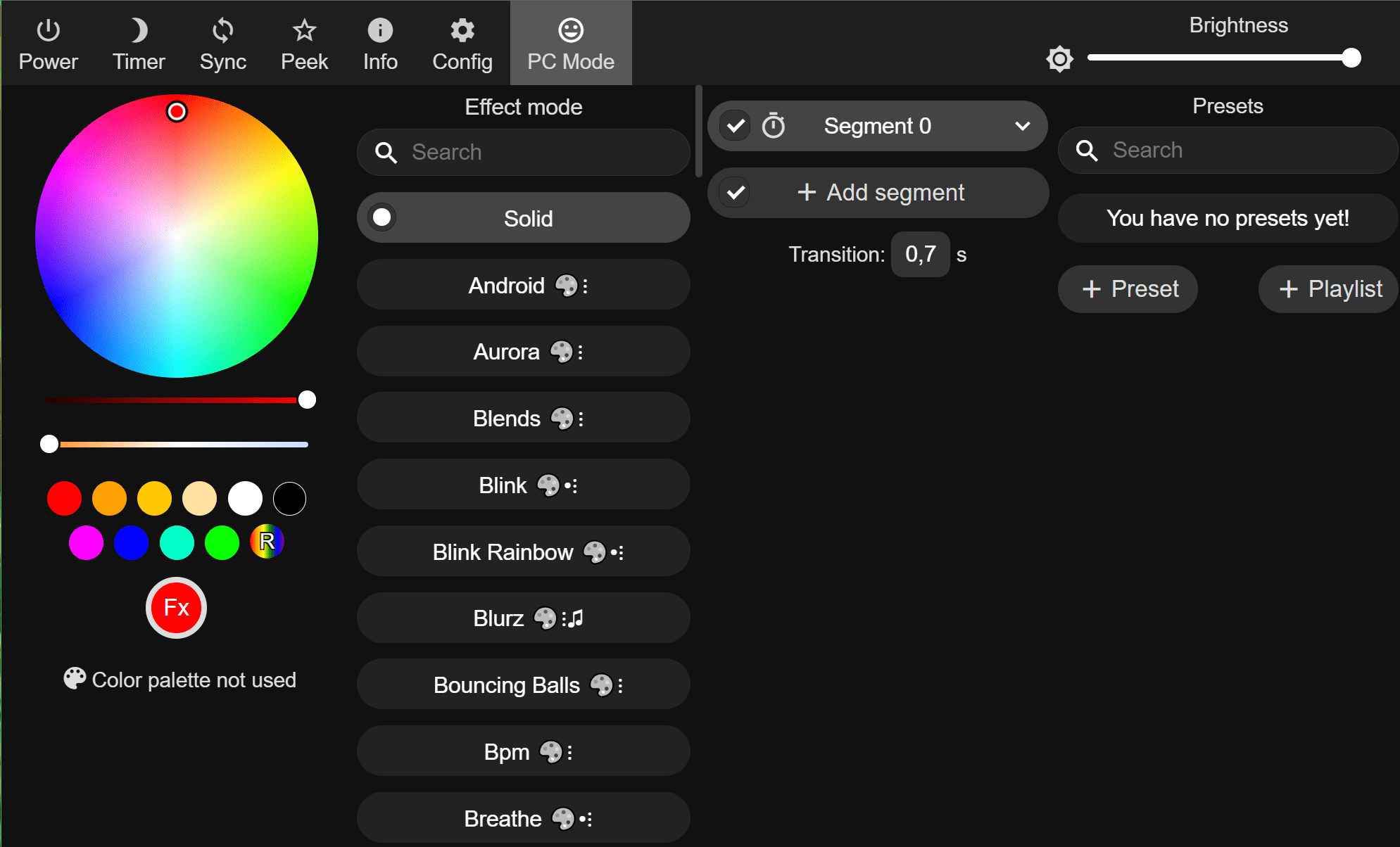
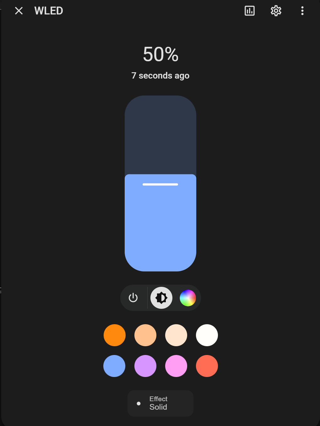
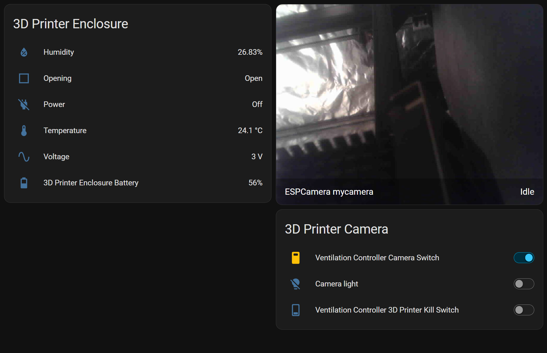
Wled UI on the left and Home Assistant integration on the right.
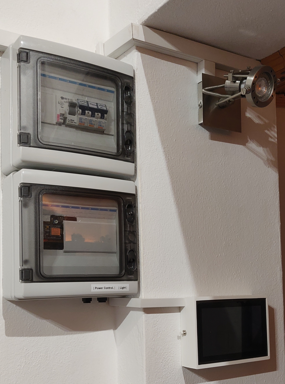
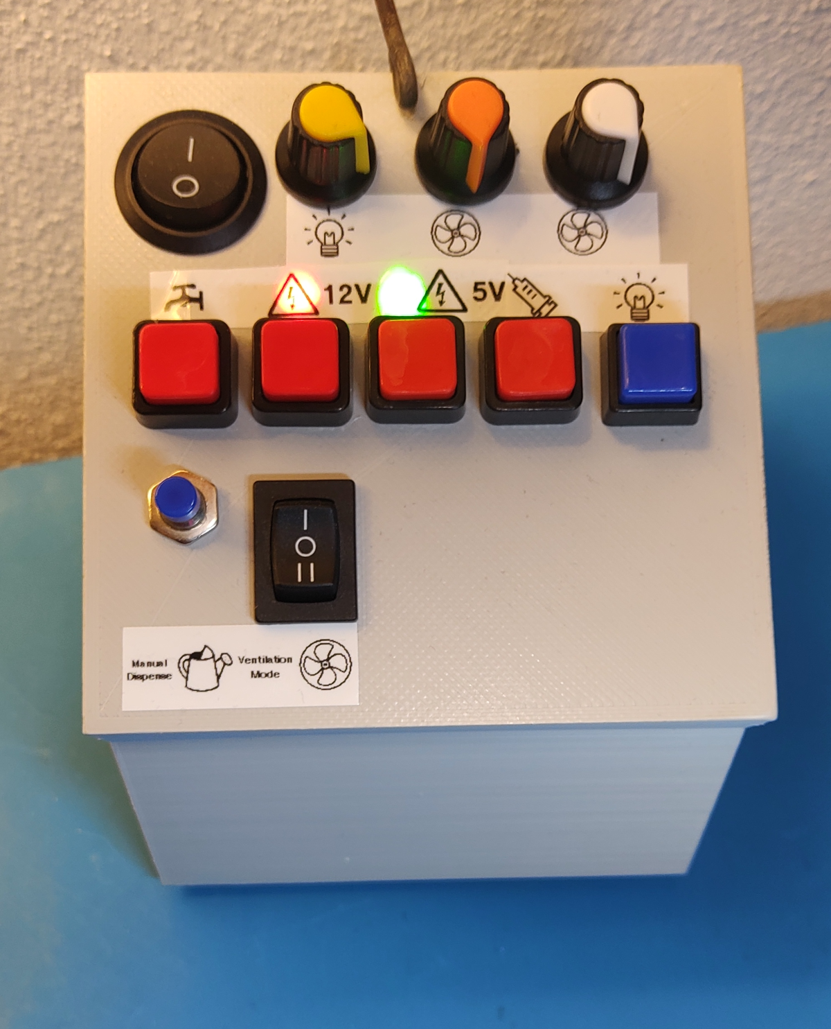
The ventilation control panel became a bit of a mess over the years as I kept changing things around. If I did it now, I would just go with a mostly digital control panel controlled directly from a website(Home Assistant/Node Red) or maybe add an ESP32 with one of those 2.8inch TFT touchscreens into the control box and make a nice UI.
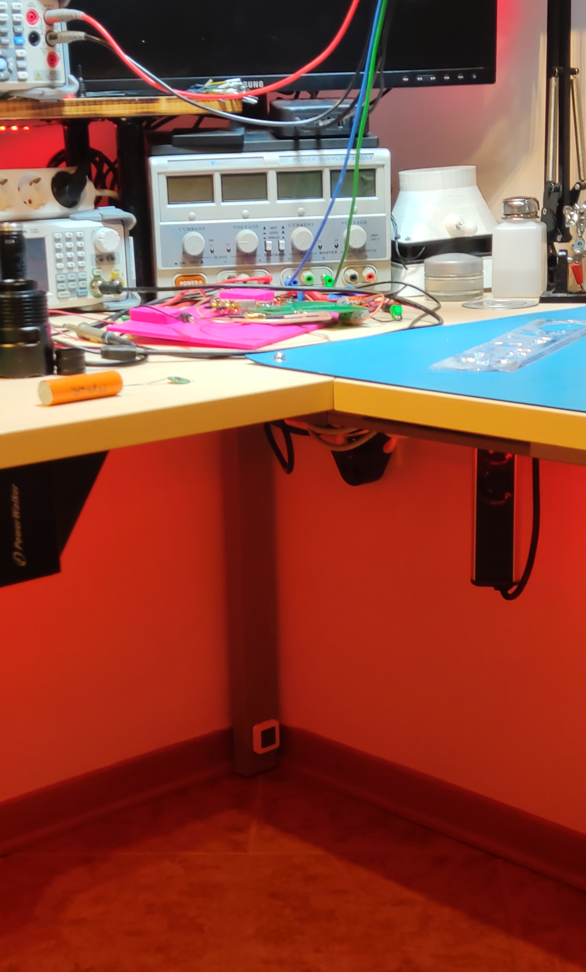
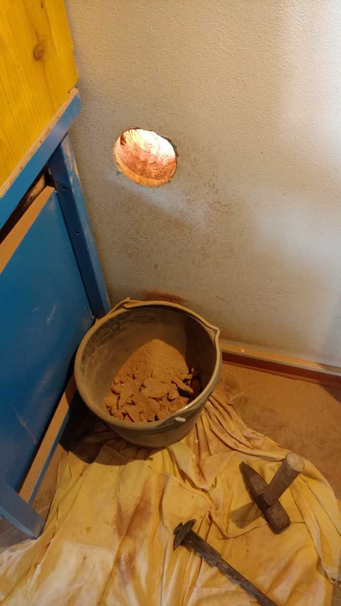
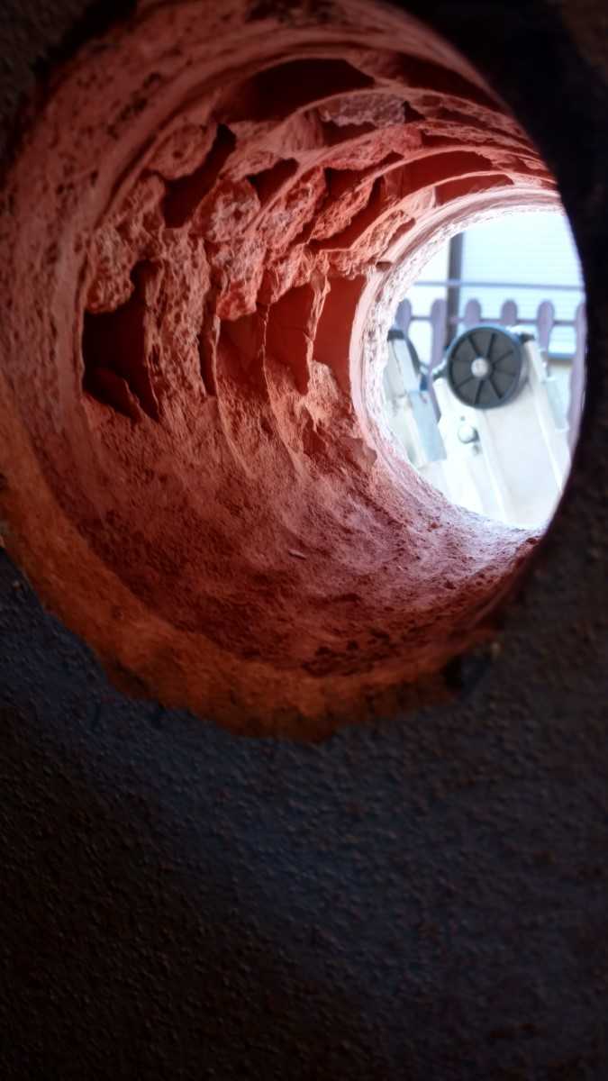
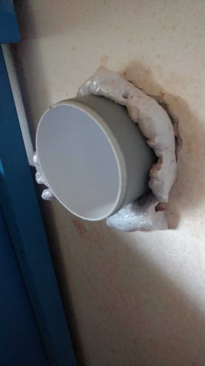
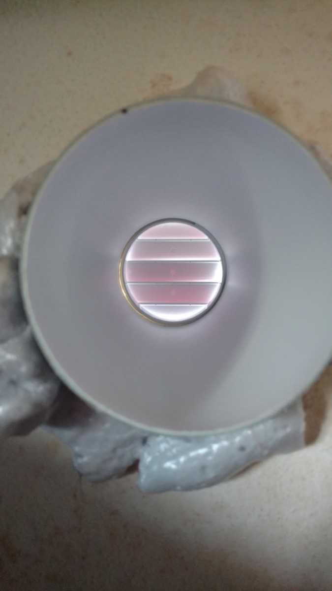
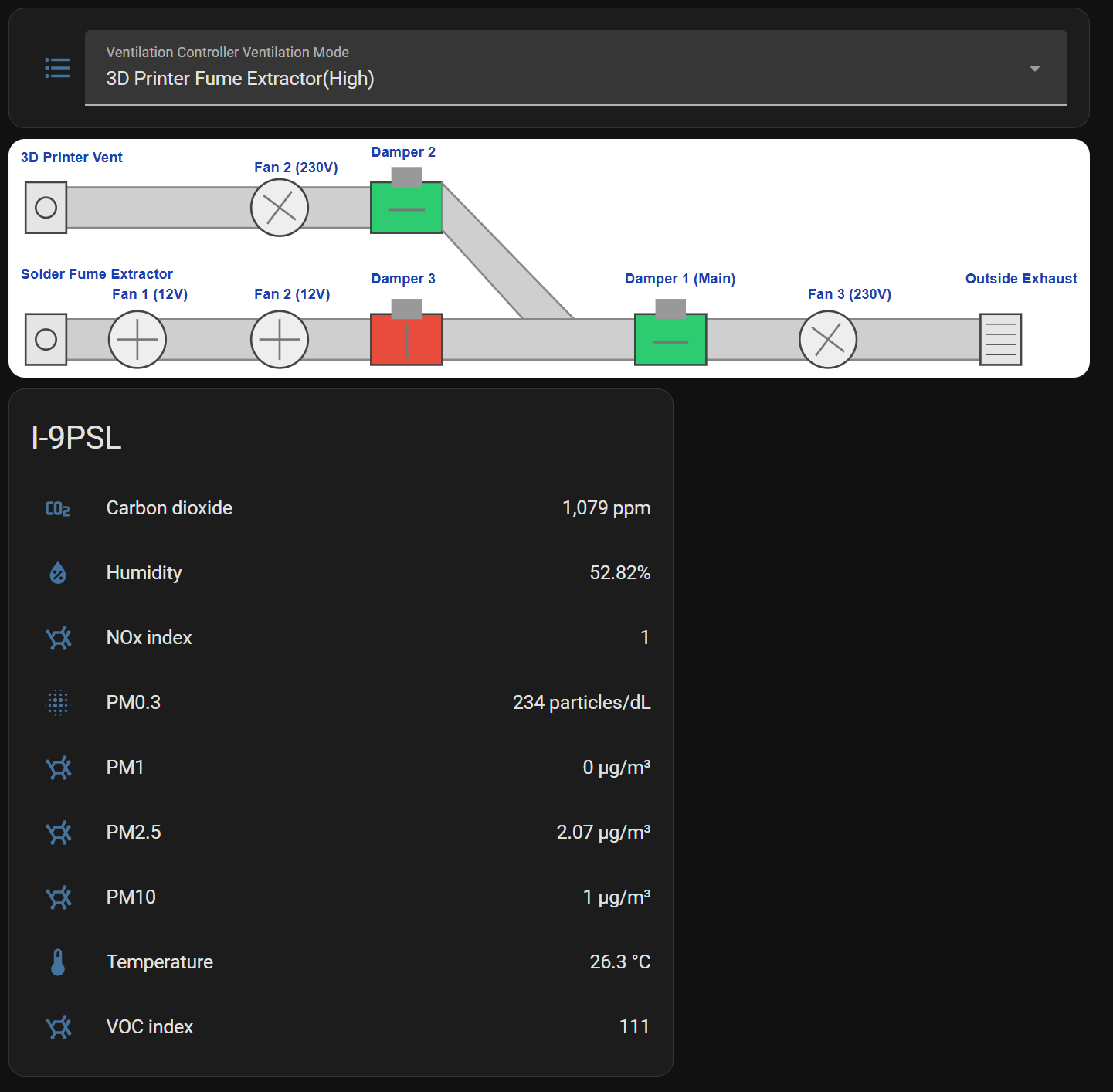
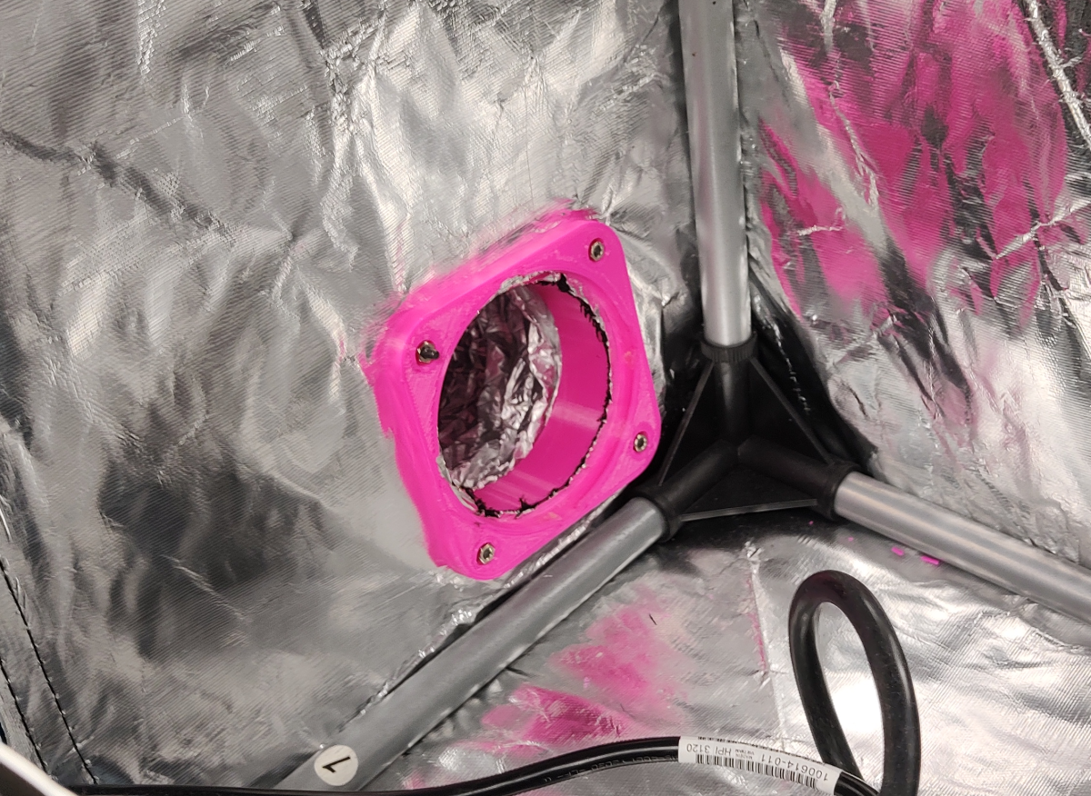
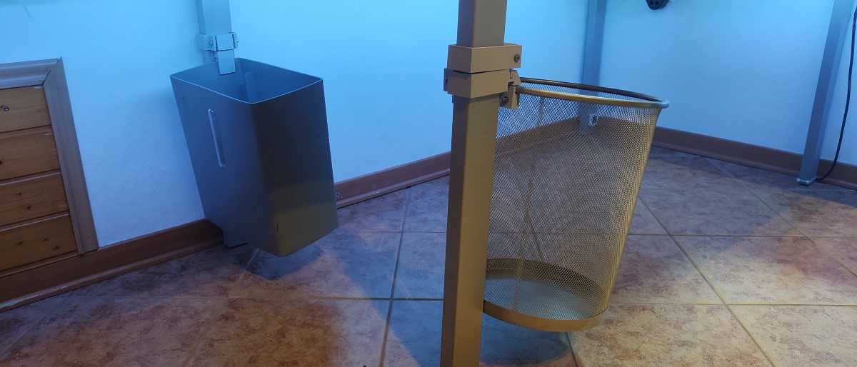
One of the air ducts can be either attached to the 3D printer enclosure for ventilation when printing or it can be detached and used on the table for soldering fume extraction.
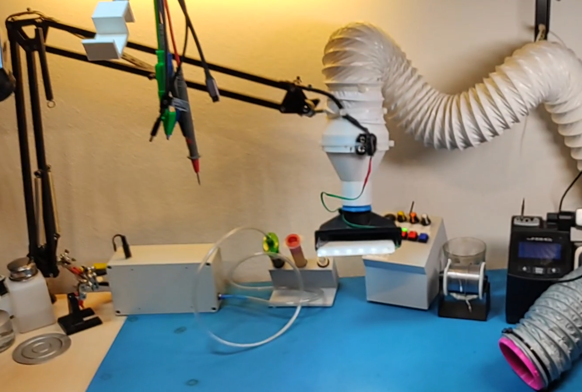
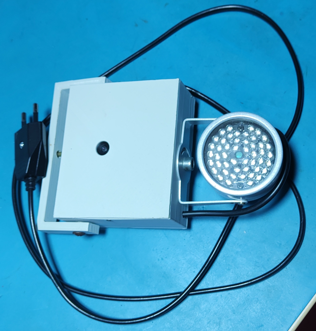
The other air duct is suspended from an old lamp arm and has replaceable attachments at the end. One attachment is a large shroud that is meant to be positioned higher over the work being done. It has LEDs for illumination and an extra extractor fan. The other attachment is made from a vacuum cleaner attachment that is meant to be positioned closer to the soldering area, for example, a PCB.
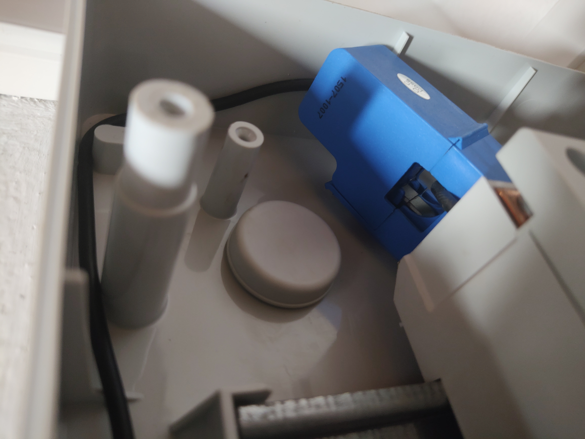
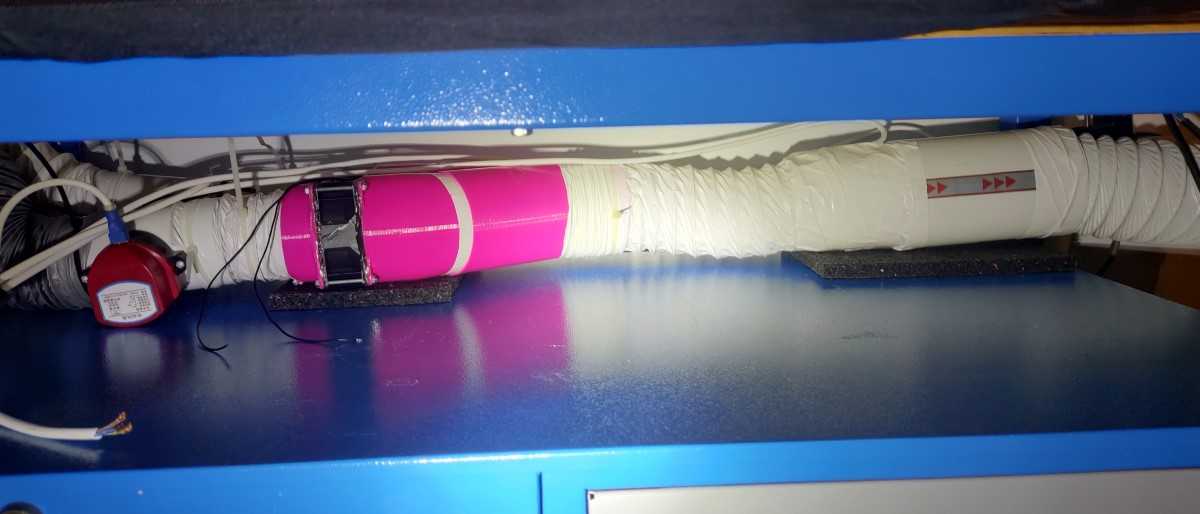
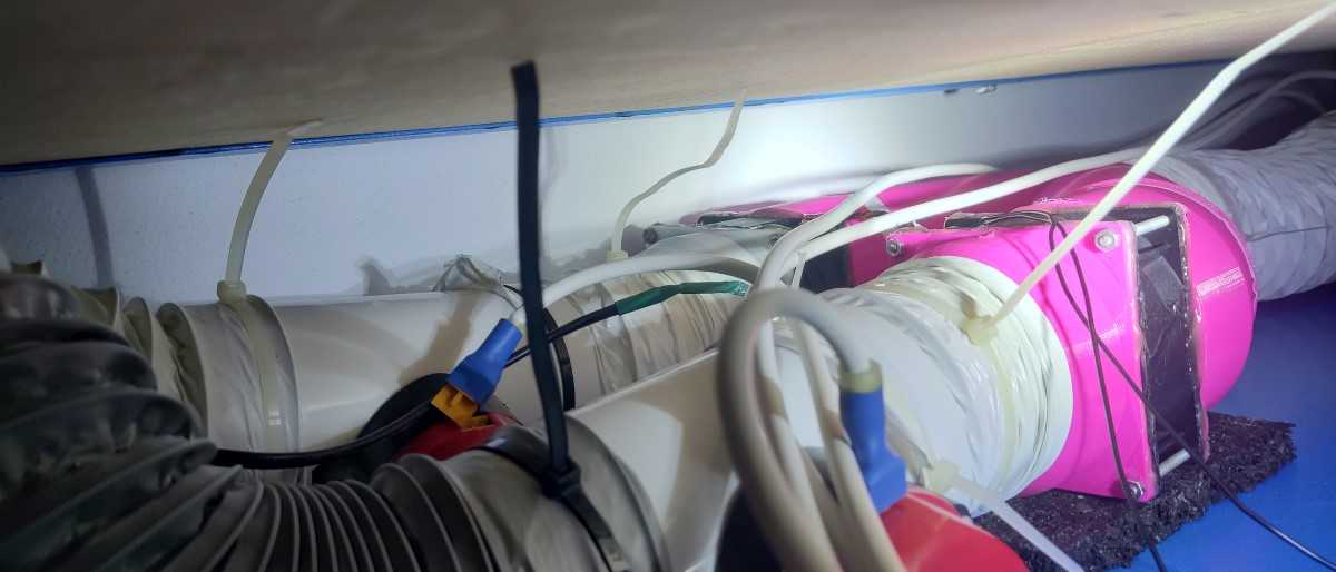
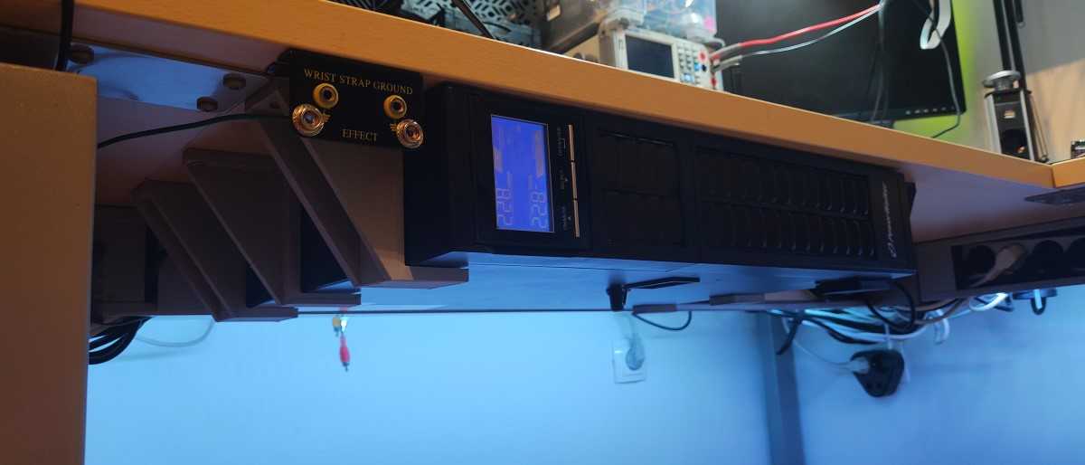
Fans, dampers and ducting under the table.
Fume extractor demonstration while soldering.
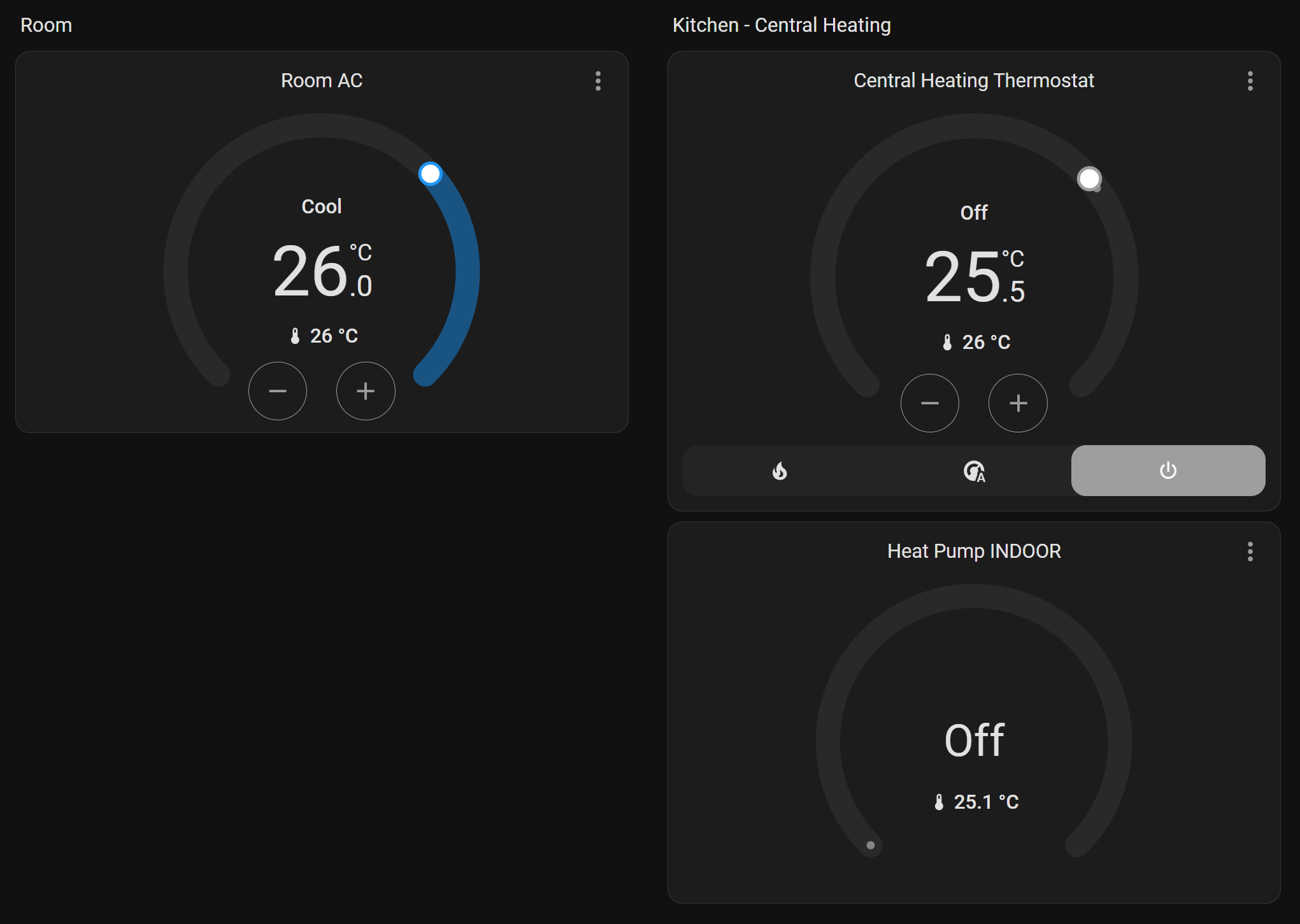
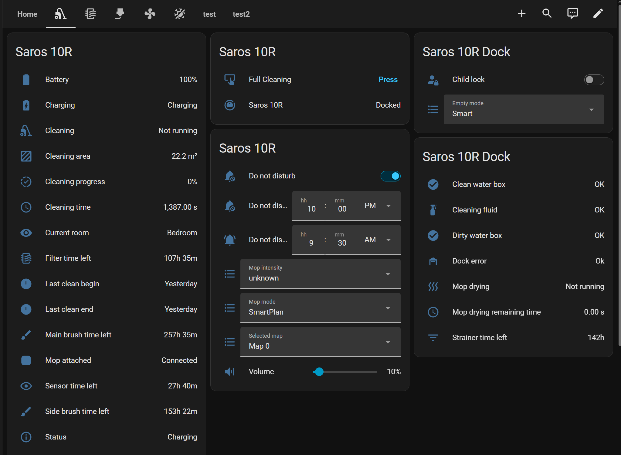
The AC and heat pump are IoT-enabled, so I’m using the integration that popped up automatically.
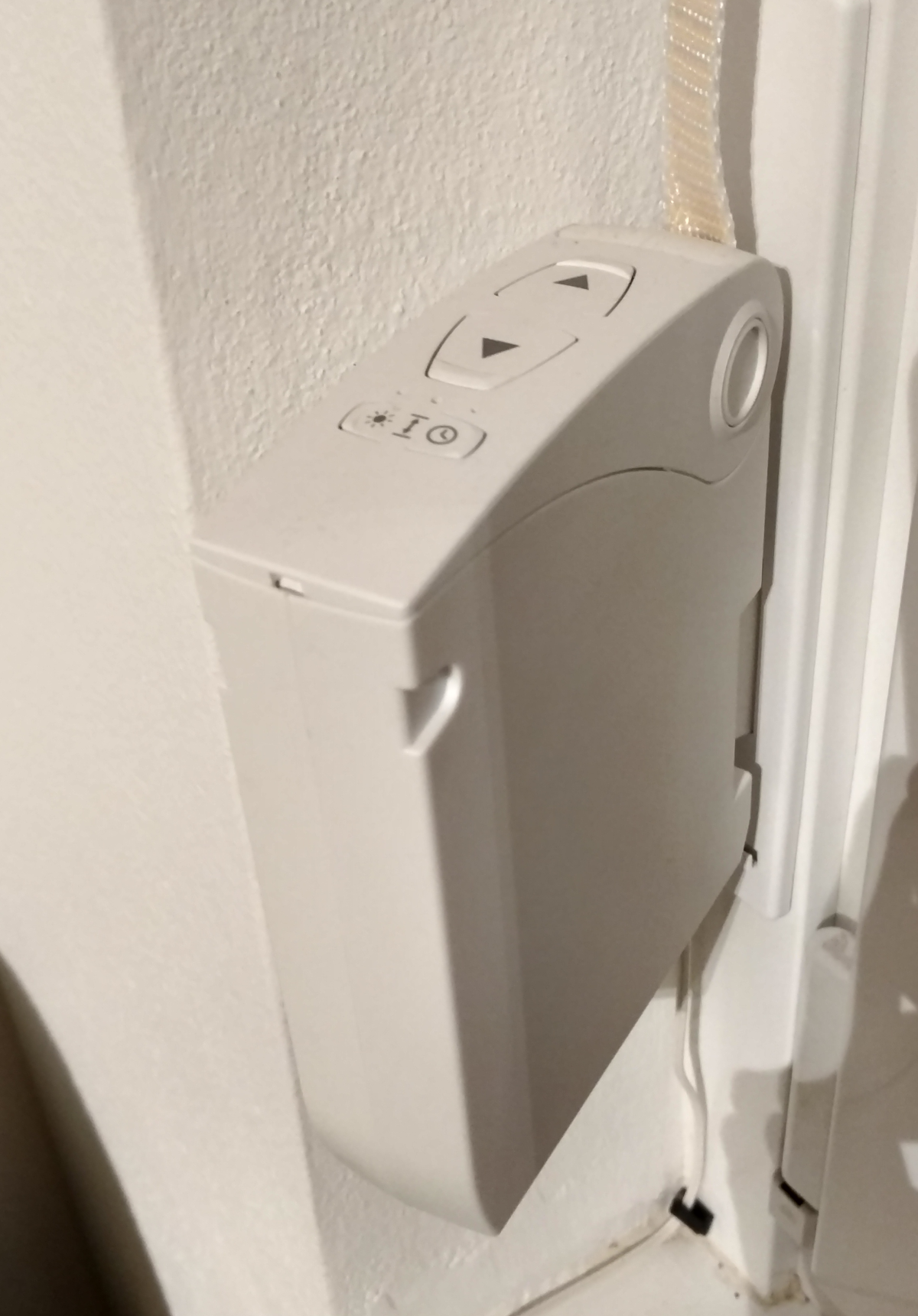
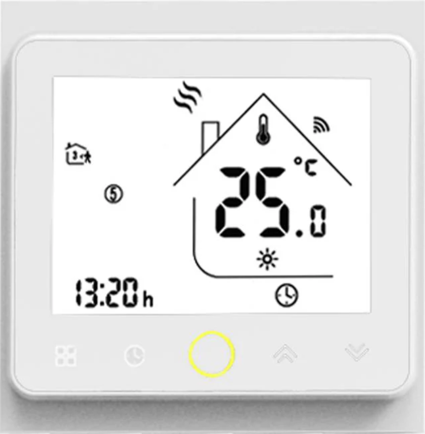
The thermostat that controls the central heating water circulation pump is a Tuya/Beca/MOES(or whatever) BHT-002. There is a Tuya integration for Home Assistant, but it requires a connection to their cloud, which I don’t like. Also, the app UI and functionality are terrible and buggy(it has been that way for years). So I decided to flash it with open-source aftermarket firmware.
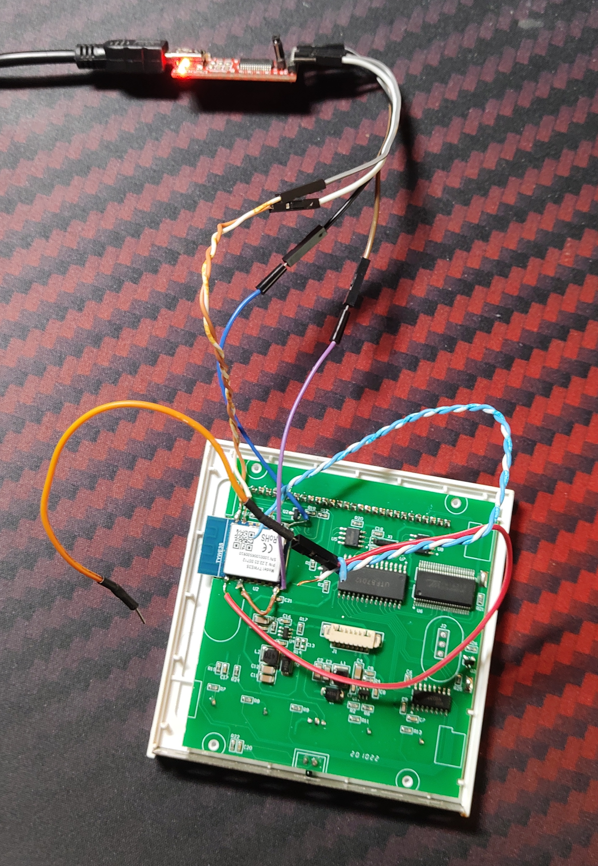
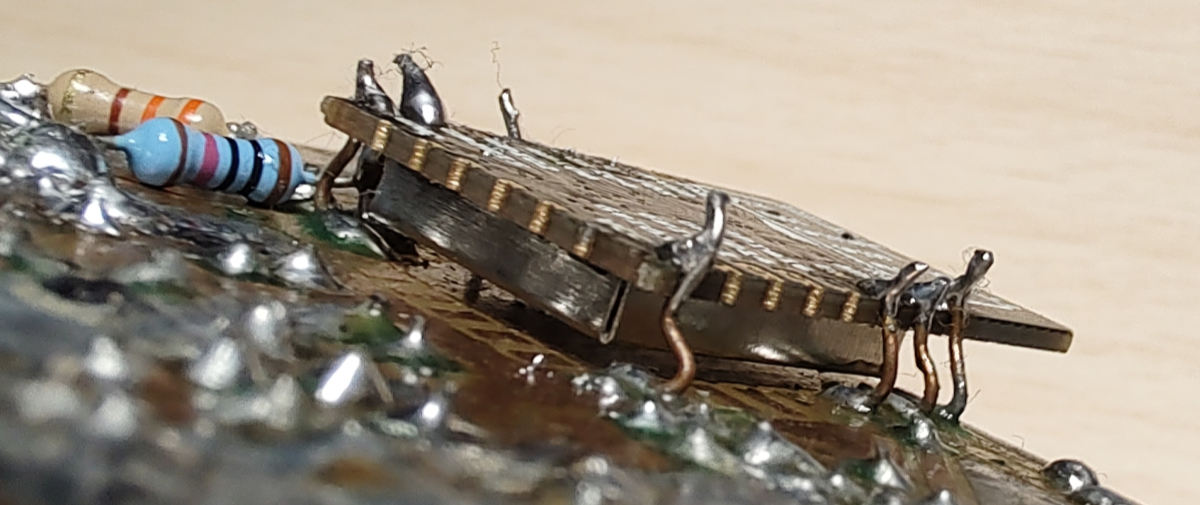
You used to be able to flash it OTA, but they disabled this in later versions of the firmware, so I had to go the physical access route and solder some wires to the ESP8266 module it uses inside.
You can install esptool in powersehll with:
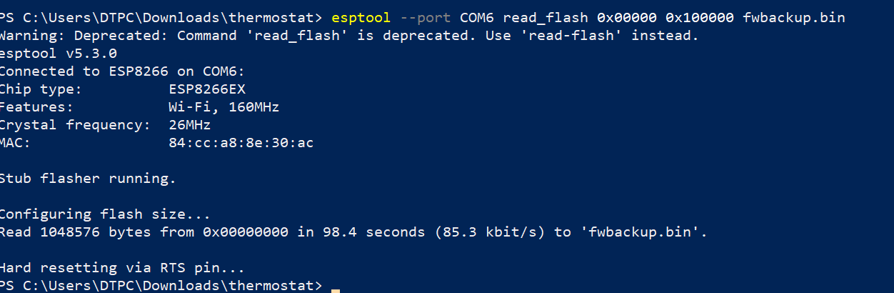
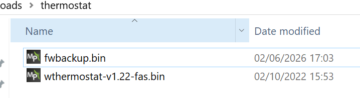
Then run(on the correct COM port of course) to backup the original firmware in case something goes wrong:
esptool –port COM6 read_flash 0x00000 0x100000 fwbackup.bin
Next, run this to erase old the firmware:
esptool –port COM6 erase_flash
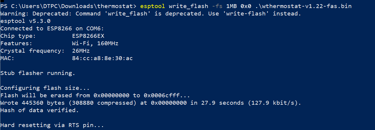
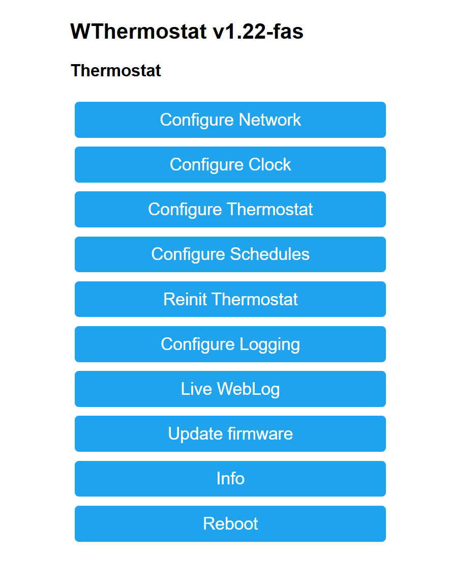
And now run this to flash the new firmware:
esptool –p COM6 write_flash -fs 1MB 0x0 .\wthermostat_1.22.bin
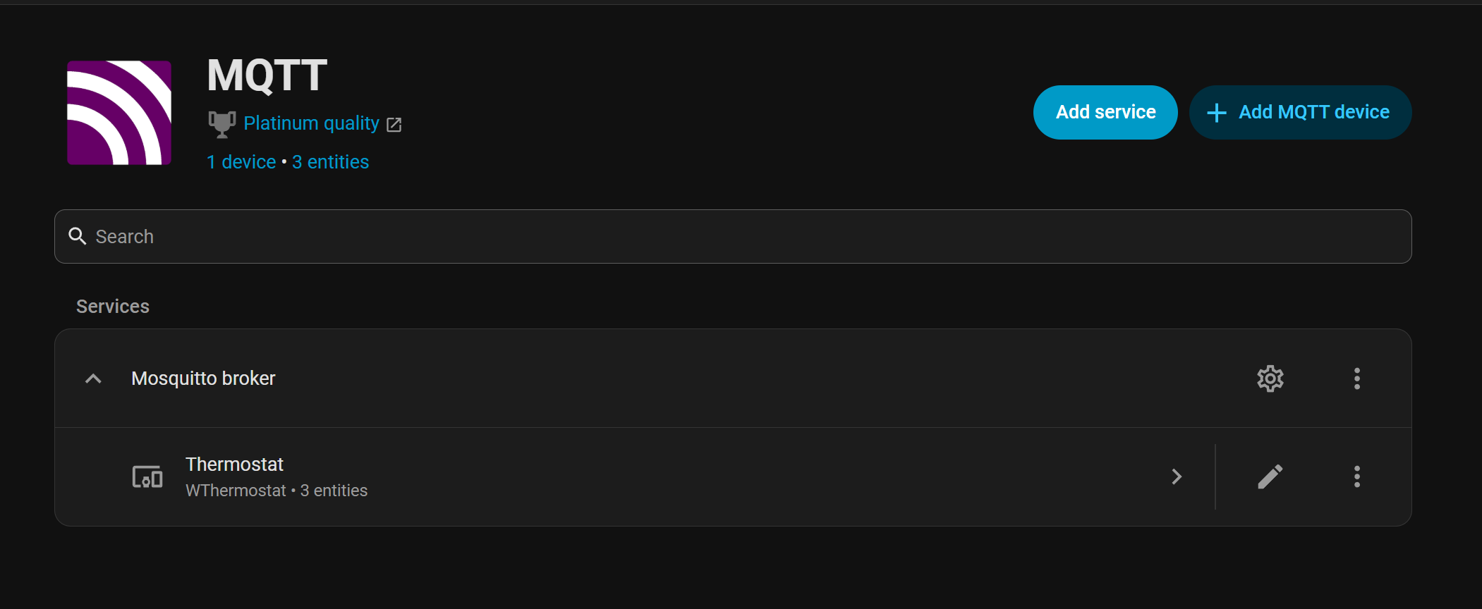
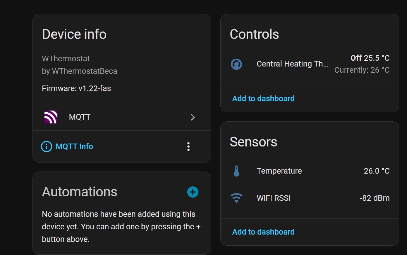
Finally, it becomes available in Home Assistant under MQTT.
I didn’t set up any IR or RF human presence sensors because I honestly don’t really see a need for them at the moment. I could use them to turn on the lights when I walk in, but this really depends on the circumstances, sometimes I just want the ambient lighting, while sometimes I want the blinds open. So most things are either run continuously, on a timer or are turned on/off by me.
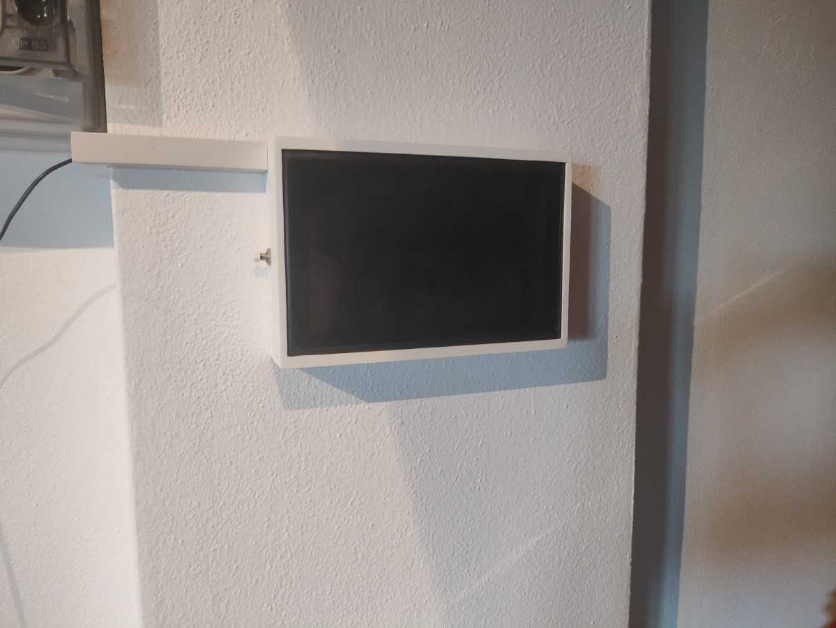
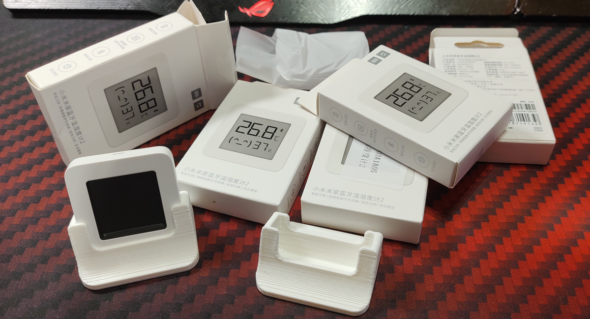
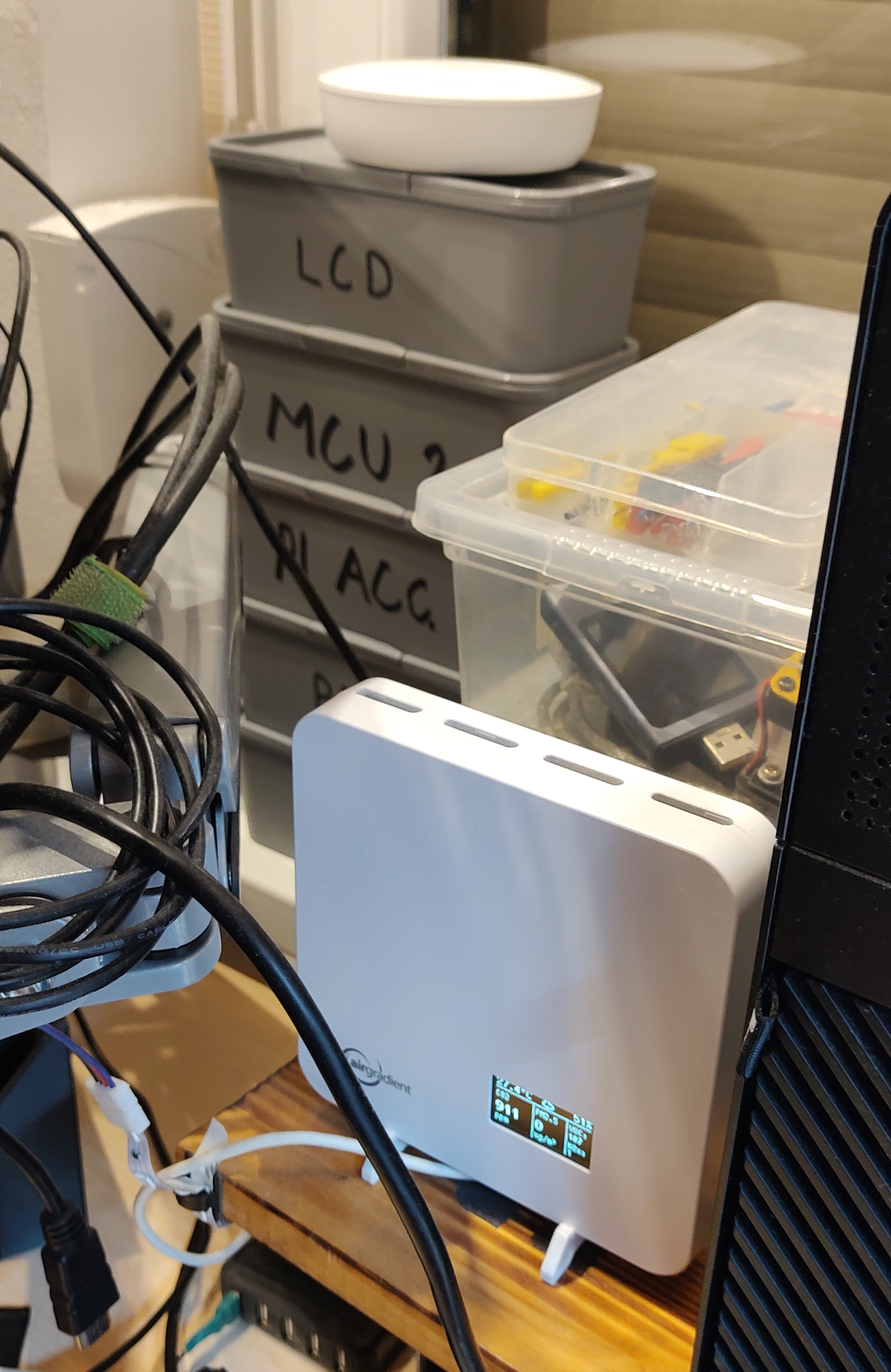
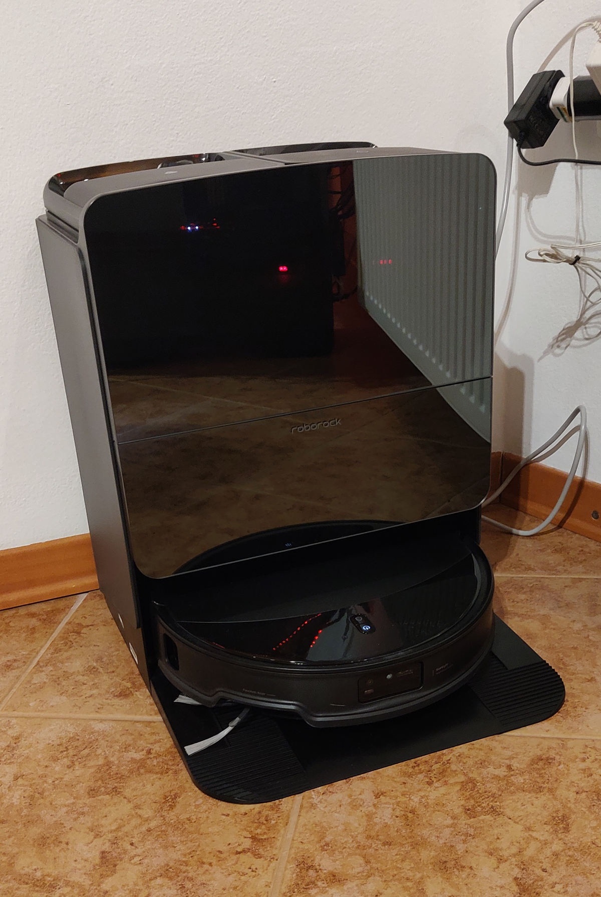
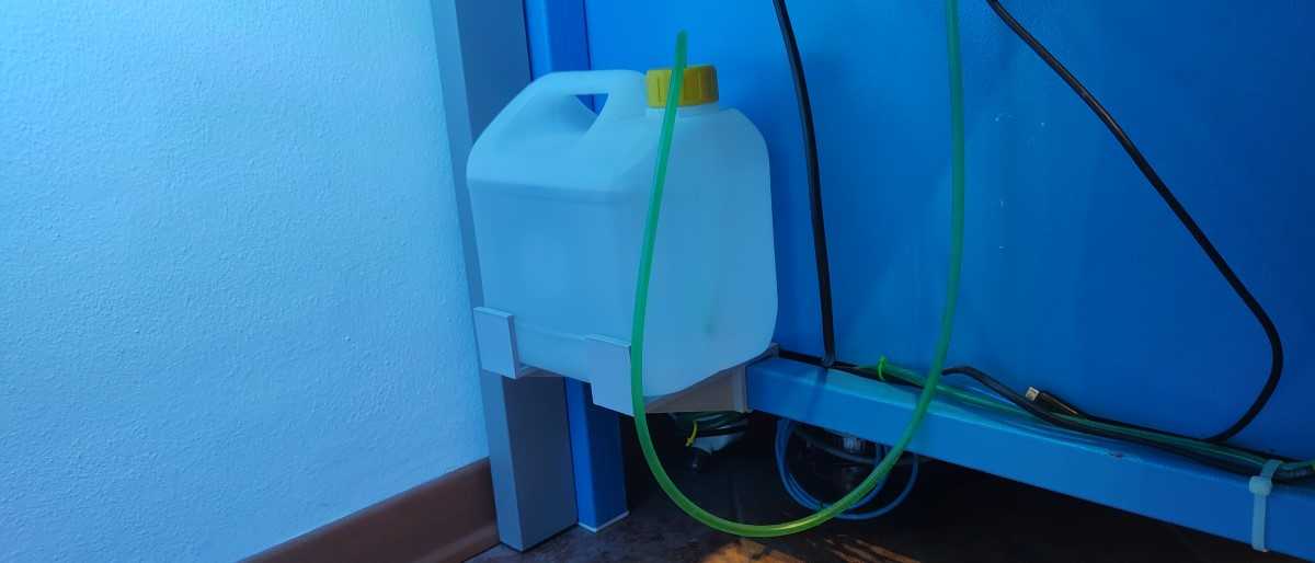
After getting the robotic vacuum cleaner, I either moved things off the floor or 3D printed mounts so I could mount them high enough for the robot to go under them.
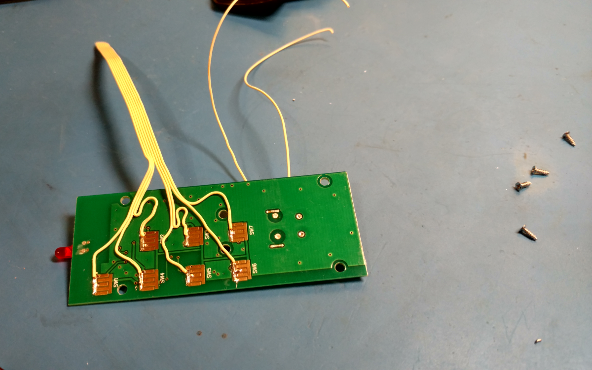
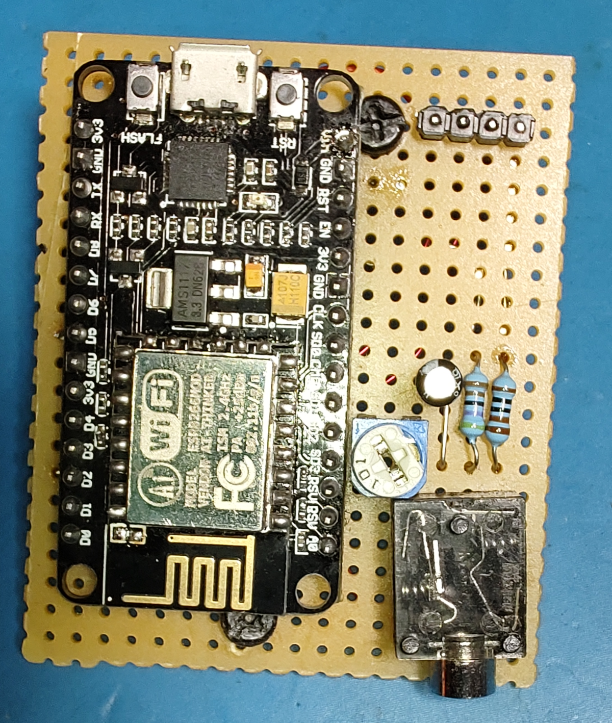
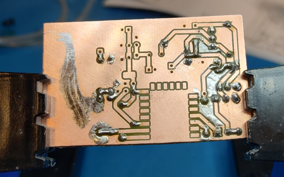
Because I forgot the current limiting resistors, the transistor was heating up too much.
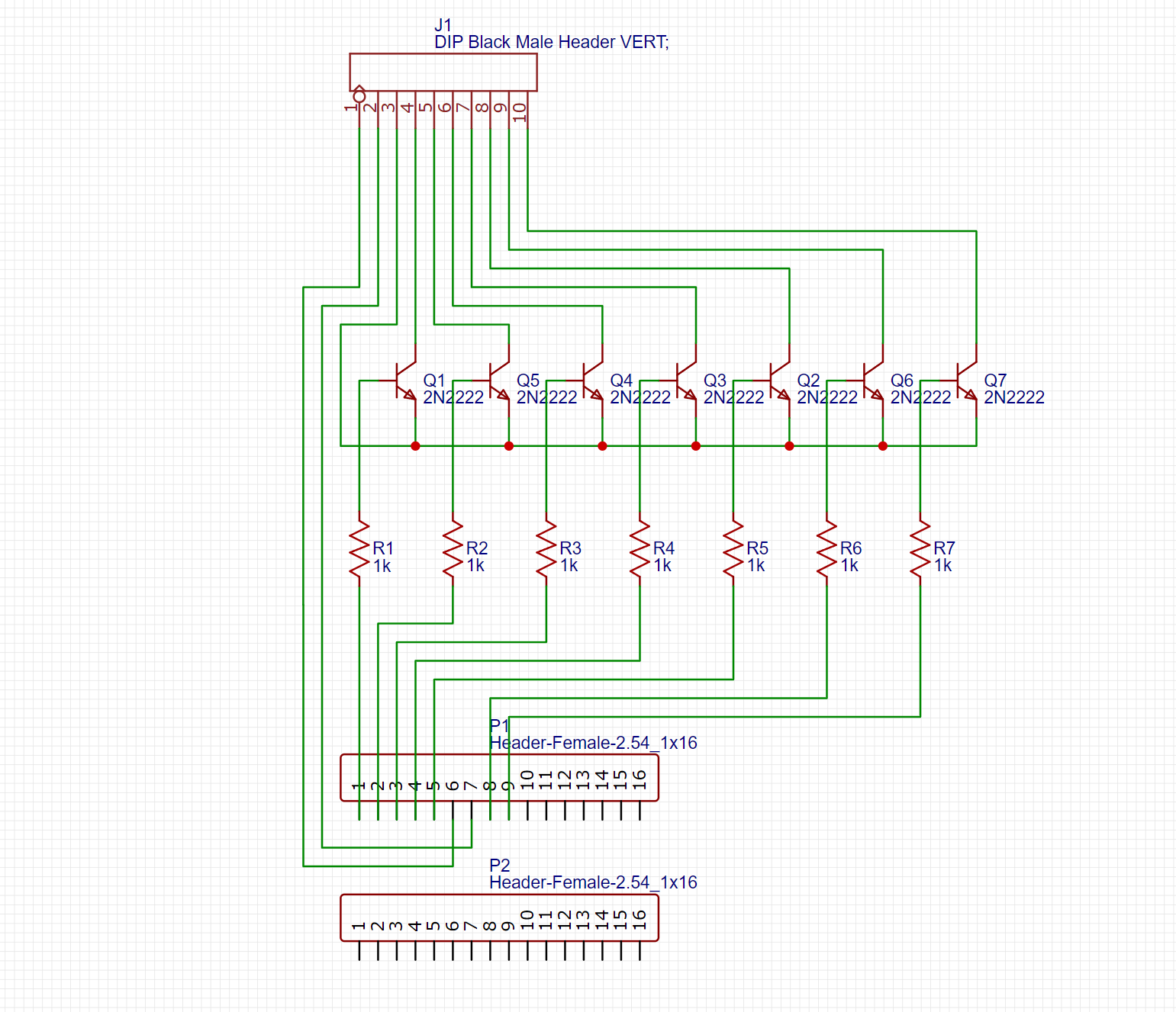
You can see the missing resistors… just hanging out on the right side of the PCB 😂. I updated the schematic, but I didn’t bother updating the PCB layout as I wasn’t going to re-etch and rebuild the damn thing. Instead, I just made a bodge repair.
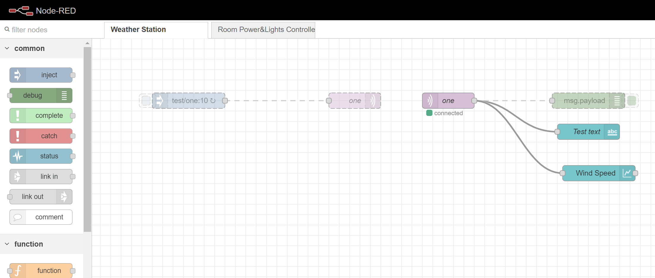
Here’s the Node-RED flow for the MQTT messages it receives from the ESP.